Introduction
The use of pneumatic cable-blowing technology for installing fiber optic cables (FOCs) in protective polyethylene ducts (PPDs) and microducts has become widely adopted worldwide. This method is particularly common in the deployment of Fiber-to-the-Home (FTTH) networks and last-mile access infrastructure.
Installing fiber optic cables within microduct systems enables network expansion as demand grows, allowing construction activities to be phased over time. When traffic volumes increase or the number of active subscribers rises, network capacity can be expanded simply by blowing additional fiber optic cables into unused ducts. This approach eliminates the need for repeated excavation work and significantly reduces future deployment costs.
Today, the duct-and-cable system is widely recognized as an effective alternative to armored cables installed directly in the ground. In addition to underground installations, protective polyethylene ducts can be deployed across water crossings, inside existing pipelines and cable conduits, on bridges and overpasses, within buildings, and in tunnels, including subway systems.
Protective ducts shield communication cables from a wide range of external influences, including mechanical damage, moisture, and rodent activity. However, constructing a fiber optic network using this method generally requires more time and a higher initial investment because installation is performed in two stages:
- Installation of the protective duct.
- Installation of the fiber optic cable within the duct.
At first glance, this may appear to increase project costs unnecessarily by requiring additional materials and labor. In practice, however, the approach often results in substantial savings because it allows the use of simpler, non-armored optical cables that are significantly less expensive than direct-buried armored alternatives.
The long-term economic benefits of this solution are one of the primary reasons for its widespread adoption in many European countries and other developed telecommunications markets.
Advantages of Protective Polyethylene Ducts
Protective polyethylene ducts offer several important advantages:
- They provide mechanical protection for fiber optic cables, allowing the use of less expensive non-armored cable designs and reducing overall network construction costs.
- Ducts are installed using methods similar to those used for optical cable installation. Because the cable is inserted after most construction work has been completed, the risk of cable damage during excavation is significantly reduced.
- Multiple ducts can be installed simultaneously, providing redundancy and enabling future network expansion without additional excavation.
- Damaged or obsolete cables can be removed and replaced without replacing the duct itself. In many cases, cable removal and replacement can be performed in a single operation by connecting the new cable to the end of the existing one.
- Ducts equipped with a permanent low-friction inner layer allow the installation of exceptionally long cable sections, in some cases exceeding 5 km between access points.
Like any engineering solution, protective duct systems have certain limitations that should be considered during network design and construction:
- Larger outside diameters and greater minimum bending radii compared with conventional fiber optic cables.
- The need for specialized installation equipment.
- Increased sensitivity to crushing forces.
- The requirement to maintain a clean and unobstructed duct pathway throughout installation.
Protective polyethylene ducts may be installed using either trenchless methods or conventional open-trench construction at ambient temperatures ranging from –10°C to +50°C. With appropriate preheating procedures, installation can also be performed at temperatures below –20°C.
Once installed, the ducts are designed to operate within an ambient temperature range of –50°C to +65°C. In general, the installation of protective polyethylene ducts follows principles similar to those used for telecommunications cable installation and should be carried out in accordance with applicable standards, technical specifications, and manufacturer recommendations.

Pic 1. Protective polyethylene duct with a permanent low-friction inner layer.
The manufactured ducts are typically available with outside diameters ranging from 25 mm to 63 mm. To reduce friction during cable installation, the inner surface may incorporate either a permanent low-friction layer or a liquid lubricant. Some duct designs also feature longitudinal internal ribs or grooves, as shown in Pic 2.

Pic 2. Protective polyethylene duct with longitudinal internal grooves.
The expected service life of buried polyethylene ducts is approximately 50 years. Ducts are supplied either on drums or in coils, typically in lengths ranging from 600 m to 4,000 m.

Pic 3. Typical coil of protective polyethylene duct.
Duct Installation
During the design phase, every effort should be made to keep the route as straight as possible. Where changes in direction are unavoidable, the route should be designed with a minimum bend radius of 2 m.
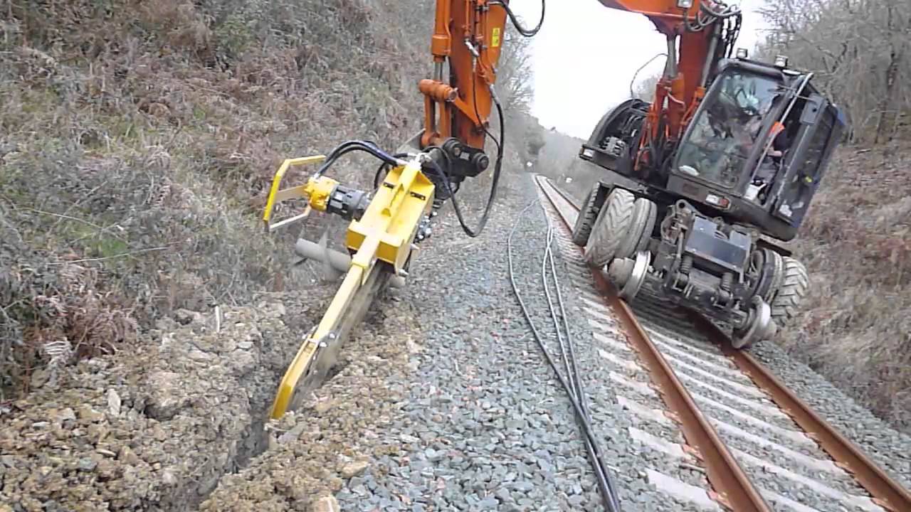
When ducts are installed using cable-laying equipment or by conventional trenching methods, sharp bends must be avoided. The recommended minimum static bend radius for an installed duct is 1.5 m (Pic 4).
As noted previously, protective polyethylene ducts may be installed at temperatures ranging from -10°C to +50°C. Installation at temperatures below -20°C is permissible if the duct is preheated beforehand.

Pic 4. Minimum allowable bend radii for protective polyethylene ducts: a) installed duct; b) duct being unwound from a drum; c) duct being laid in a trench.
Ducts should be installed in the longest practical continuous lengths in order to minimize the number of joints. Joint locations should be determined during the design phase based on route optimization. Additional joints should only be introduced when operationally necessary.
The selection of couplings used to join duct sections must take into account the planned method of cable installation. Both mechanical and electrofusion couplings may be used (Pic 5). Installation procedures must follow the manufacturer’s instructions.


Pic 5. Couplings for joining duct sections: a) mechanical coupling; b) electrofusion coupling.
In areas subject to significant temperature fluctuations, expansion couplings should be installed to accommodate thermal expansion and contraction of the duct system (Pic 6).

Pic 6. Expansion coupling for protective polyethylene ducts.
For buried installations, a warning tape should be placed approximately 0.5-0.7 m below ground level above the duct route. The tape should include continuous identification markings indicating the presence of underground telecommunications infrastructure.
Electronic markers or equivalent locating devices should be installed at duct joints and other key locations to facilitate route tracing and future maintenance activities (Pic 7). This is particularly important when fully dielectric fiber optic cables are used, as such cables cannot be located using conventional metallic cable-tracing equipment.


Pic 7. Examples of electronic route markers.
During installation, the length of each duct section should be recorded using the manufacturer’s length markings.
When multiple ducts are installed within the same trench, they should be arranged side-by-side rather than stacked vertically. Installation in two layers is recommended only where trench width is restricted and more than ten ducts must be accommodated.
The trench depth must allow for a bedding layer of sand or loose soil approximately 10–15 cm thick to provide a level base for the duct.
The trench bottom should be free of stones, large clay clods, and rock fragments. Where large rocks or immovable obstacles are present, care must be taken to prevent excessive bending or crushing of the duct.
At route changes involving a 90-degree turn, the duct must be installed with a minimum bend radius of 2 m. If trench dimensions do not permit this radius, the corner should be widened or excavated accordingly. After installation, the bend should be secured using soft backfill material and properly compacted.
Methods for Installing Fiber Optic Cable in Protective Ducts
Fiber optic cable should be installed only when the ambient temperature is above –10°C.
During hot weather, cable reels should be protected from direct sunlight. Excessive heating can soften the cable jacket, increasing friction inside the duct and reducing the maximum installation distance.
At locations where two duct sections are joined, the mechanical coupling may be temporarily removed to allow cable insertion. A temporary extension fitting can then be attached and brought above ground level to facilitate cable feeding and blowing operations (Pic 8).

Pic 8. Temporary extension of the duct for cable blowing operations.
Fiber optic cables can be installed using one of the following methods:
- Manual pulling.
- Mechanized pulling using a winch.
- Piston-assisted pneumatic blowing.
- Pistonless pneumatic blowing.
- Installation of ducts with the cable pre-installed.
After cable installation, splice locations are typically protected within an underground access chamber. Cable ends are joined using a fiber optic splice closure housed within the chamber.

Pic 9. Typical underground fiber conduit access chamber.
Pulling Fiber Optic Cable into Ducts
Cable pulling is the simplest and most economical installation method. A pull rope may be used either manually or with specialized pulling equipment. However, installation distances achievable by pulling are generally much shorter than those possible with pneumatic blowing – typically about half as long. As a result, cable pulling is less suitable for long-haul or backbone fiber networks. Under normal conditions, pulling distances rarely exceed 1 km per installation section without approaching the cable’s maximum allowable tensile load.
Before installation begins, a pull rope or draw line must already be present inside the duct. If no draw line is available, one can be installed by blowing a lightweight guide line through the duct using compressed air.
Prior to pulling, the cable should be fitted with an appropriate pulling attachment:
- A pulling eye attached to the central strength member, where applicable.
- A pulling sock or mesh grip for cables designed to be pulled by the outer jacket.
The primary advantage of mechanized pulling over manual installation is the ability to maintain a controlled and constant pulling force. This minimizes sudden load variations and reduces the risk of exceeding the cable’s allowable tensile limits.

Pic 10. Typical fiber optic cable suitable for mechanized pulling.
As shown in Pic 10, cables intended for duct installation often feature relatively simple and cost-effective constructions. Tensile loads are carried by integrated strength members, allowing the use of lightweight cable designs while maintaining adequate mechanical performance.
Pneumatic Cable Blowing
Pneumatic blowing is the preferred method for installing fiber optic cables over long distances and is capable of achieving installation lengths of several kilometers in a single operation. The achievable blowing distance depends on several factors:
- The ratio between cable diameter and duct inner diameter.
- Cable weight.
- The coefficient of friction between the cable jacket and the duct wall.
- Cable stiffness.
- Ambient temperature.
- Route geometry, including curves and bends.
- Elevation changes along the route.
- Duct alignment and curvature within the trench.
- Compressor performance and air-flow characteristics.
For optimum performance, the cable-to-duct diameter ratio should be approximately 1:2. Although smaller ratios can improve blowing efficiency, ratios below 1:3 are generally not recommended because the cable may form loops within the duct, increasing the risk of installation failure or cable damage. Recommended cable characteristics include:
- Weight: 0.1-0.3 kg/m.
- Stiffness: 1-3 N/m².
All pneumatic blowing operations must be carried out in accordance with the equipment manufacturer’s operating instructions and safety requirements. Before installing a second cable in an occupied duct, the following factors should be considered:
- Risk of damaging the existing cable during access to the duct.
- Friction occurs primarily between cable jackets rather than between the cable and the duct wall.
- Even when multiple cables are installed, the operation remains sequential rather than simultaneous.
- Installation distances for subsequent cables are substantially shorter, often limited to approximately 500 m, resulting in increased labor and additional access points.
These factors generally make the installation of multiple cables in a single duct less efficient than installing separate ducts during the initial construction phase.
Piston-Assisted Pneumatic Blowing
In piston-assisted systems, cable installation is achieved through the combined action of two forces:
1. Pulling force generated by a piston (or parachute) attached to the cable end and propelled by compressed air.
2. Additional mechanical pushing force provided by the cable-feeding unit.
By controlling compressor pressure and feed force, operators can accurately regulate the load applied to the cable throughout the installation process.
The piston diameter should be slightly smaller than the duct’s inner diameter to minimize friction losses. The tensile load imposed on the cable by the piston must be calculated in advance to ensure compliance with the cable manufacturer’s specifications.
The combined action of the pneumatic pulling force and the mechanical feeding force allows precise control of the loads applied to the cable during installation. By adjusting compressor pressure and feed force, operators can optimize installation performance while ensuring that the cable remains within its allowable mechanical limits.
Using a cascade blowing arrangement, it is possible to install an entire cable length of 4-8 km without intermediate figure-eight storage loops. This is accomplished by positioning multiple blowing units at strategic locations along the route, allowing installation to proceed continuously from one section to the next.

Pic 11. Schematic diagram of cascade pneumatic cable blowing.
Blowing fiber?
Now take care of your splice records!
Trusted by 2,000+ ISPs and fiber techs around the world
Pistonless Cable Blowing Technology
Among all available installation methods, pistonless pneumatic blowing is generally regarded as the most efficient. This section examines the technology in greater detail.
The method is based on maintaining the fiber optic cable in a partially suspended state as it travels through the duct. This is achieved by creating an aerodynamic “air cushion” around the cable. As a result, the force acting on the cable is distributed more evenly, reducing mechanical stress during installation.
The air-cushion effect provides several important advantages:
- Uniform distribution of installation forces along the cable.
- Reduced risk of cable overload during unexpected interruptions and subsequent restarts.
- Elimination of concentrated tensile forces at the cable end.
- Increased installation distances and higher installation speeds.
Under normal operating conditions, average blowing speeds can reach 90 m/min.
The cable is fed into the duct by a drive mechanism that initially stabilizes and guides the cable while providing additional pushing force throughout the installation process. This supplementary force significantly increases the achievable blowing distance.
From a mechanical perspective, a fiber optic cable behaves similarly to a flexible string with finite stiffness. When pushed through a tubular channel, the cable naturally tends to assume a helical shape, causing friction against the duct walls.
As the installation distance increases, friction also increases, eventually making further advancement impossible.
The introduction of high-velocity airflow dramatically changes this behavior. The turbulent boundary layer generated around the cable effectively carries it through the duct. Once a certain airflow velocity is reached, aerodynamic forces cause the cable to straighten and move toward the center of the duct.
In this state, the cable effectively “floats” within the airflow, with minimal contact with the duct walls. The resulting reduction in friction allows installation over much greater distances than would otherwise be possible.

Pic 12. Cable behavior with and without airflow during installation.
The cable-feeding mechanism located at the duct entrance performs two essential functions:
1. Unwinding the cable from the reel.
2. Providing the mechanical thrust required to assist cable movement through the duct.
Historically, feeding systems utilized dual-track mechanisms that gripped the cable firmly between two moving tracks. Modern equipment increasingly employs roller-based feed systems, which are simpler, more compact, easier to maintain, and generally more reliable. A typical blowing machine configuration is illustrated in Pic 13.

Pic 13. Schematic diagram of a cable blowing machine connected to a duct.
A cable blowing machine, often referred to as an injector, is a compact device designed to control and automate the installation of fiber optic cables into ducts and microducts. Its primary functions include:
- Aligning the cable and duct axes.
- Feeding the cable into the duct.
- Applying cable lubricant when required.
- Measuring installed cable length.
- Controlling installation speed.
- Regulating air pressure.
- Protecting the cable by automatically stopping the feed mechanism if excessive bending or obstruction is detected.
Cable blowing machines provide a high level of process automation and significantly improve installation efficiency. They are generally compact, reliable, and easy to operate.
Most modern systems incorporate integrated monitoring and control functions that continuously supervise installation parameters and alert the operator if preset limits are exceeded.
A typical cable blowing machine consists of the following components:
- Control Unit. The control unit manages lubrication, feed speed, and cable feed force.
- Length Counter. Displays the length of cable installed during the operation.
- Compressed Air Connection. Provides the interface between the machine and the compressor supplying the airflow.
- Guidance System. A set of rollers or guides that align the cable before it enters the injector.
- Drive System. The mechanism responsible for feeding and advancing the cable.
- Injector Head (Blowing Head). A specialized assembly that creates a sealed connection between the duct and the compressed air supply.
The cable enters the duct through the injector head, which prevents dirt and debris from entering the installation system.
Cable blowing machines vary primarily in the following characteristics:
- Supported cable diameter range.
- Feed mechanism type (belt, track, or roller drive).
- Maximum installation distance.
Typical blowing distances range from 500 m to 3,000 m per installation section. Modern blowing machines are designed for operation by a single technician and offer a combination of reliability, ease of use, and low maintenance requirements. When selecting equipment, consideration should be given to:
- Build quality.
- Available functionality.
- Maintenance requirements.
- Availability of spare parts and technical support.

Pic 14. Typical CableJet cable blowing machine.
Because pneumatic blowing does not rely on cable tension to advance the cable, the risk of cable failure due to excessive pulling forces is virtually eliminated. This allows the use of lightweight, economical cable designs, including cables that contain minimal or no dedicated tensile-strength elements.
Installation of Fiber Optic Cable in Microduct Systems
In addition to conventional protective ducts designed to house one or occasionally two fiber optic cables, multi-channel duct systems have become increasingly common. These systems contain multiple small-diameter ducts, typically referred to as microducts. Individual microducts may have diameters as small as 5 mm and are designed to accommodate a single microcable.
The number of microducts contained within a single outer sheath can vary significantly depending on network requirements. Such assemblies are often referred to as microduct bundles or multi-duct systems, although the term tubular cable is also used in some technical literature.

Pic 15. Examples of multi-channel microduct system designs.
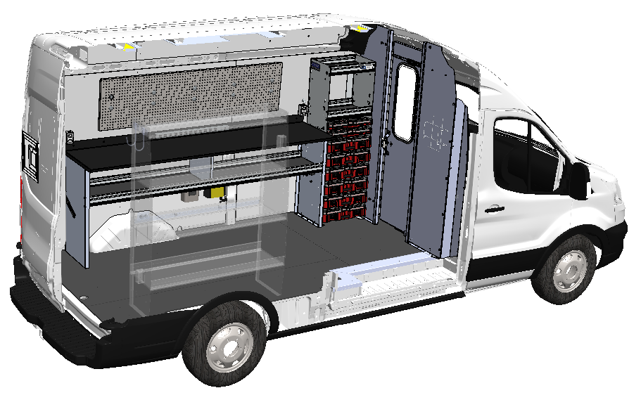
Microduct technology is particularly well suited to densely populated urban environments. Unlike conventional duct systems, microduct networks require only narrow and shallow trenches. In many cases, armored polyethylene microduct bundles can be installed directly in microtrenches approximately 30 cm deep. Microduct systems can also be installed:
- Within roads and highways.
- Along railway corridors.
- Inside buildings.
- Within utility corridors and existing infrastructure pathways.
For indoor installations, individual microducts may be grouped and secured together using tape or dedicated fastening systems. One of the major advantages of microduct technology is its flexibility. Provided that minimum bend-radius requirements are maintained, the number of bends along the route is effectively unrestricted. Under favorable conditions, installation speeds may reach 50 m/min.
To minimize friction, microducts are typically manufactured with low-friction inner coatings similar to those used in larger polyethylene ducts. Many designs also incorporate corrugated or ribbed internal surfaces. Successful microcable installation requires the following equipment:
- A source of compressed gas.
- A motorized blowing head with compressed-air connections.
- Couplings and branching components.
- Equipment for testing duct integrity.
- Sealing devices for unused channels.
The compressed gas source may be either:
- A portable compressor.
- A compressed-air cylinder.
In some cases, nitrogen can be used instead of air. To prevent moisture contamination, the gas supply should always include an appropriate drying unit. Most feed heads feature a hinged housing that simplifies cable insertion before installation begins.
The drive mechanism is typically electrically powered and may be integrated into the blowing machine or supplied as a separate external unit.
Microduct sections are commonly joined using compact couplings equipped with O-ring seals. Installation is straightforward: the microduct ends are cut square and inserted into opposite sides of the coupling body. Many couplings are manufactured from transparent plastic, allowing visual confirmation of correct installation.
At branching locations, Y-couplers are used. Because microducts have relatively large minimum bend-radius requirements, branch fittings are generally designed with smooth Y-shaped geometries rather than sharp-angle junctions. These fittings typically feature split housings and replaceable end seals, allowing repeated installation and maintenance without replacing the entire assembly.

Pic 16. Y-coupler for microduct branching.
Because compressed-air consumption is relatively low, large compressor systems are often unnecessary. In many cases, one or two portable compressed-gas tanks – similar in size to scuba tanks – provide sufficient capacity for installation work. Likewise, the feed mechanism requires only modest driving force. As a result, many compact blowing systems can be powered by a standard cordless drill or screwdriver connected directly to the feed-head drive shaft.


Pic 17. Compact cable blowing system powered by a cordless drill.

Written by Vasiliy Grodetskiy | CTO of Splice.me
With over 20 years of experience in fiber network engineering, Vasiliy has been directly involved in the evolution and deployment of fiber infrastructure worldwide. Vasiliy brings deep expertise in industry standards, regulatory environments, and the practical trade-offs between different approaches to fiber network roll-out.