Selecting the right route for a fiber optic line helps achieve an optimal balance between construction costs, reliability, durability, and long-term operational performance. Particular attention should be paid to minimizing earthworks on sections with numerous short track segments between railway stations. Requirements regarding the clearance dimensions of structures and buildings must also be met to ensure normal operation of the fiber optic line.
When designing the route, the number of optic cable crossings with the railway should be minimized, and crossings should be located in areas with the fewest tracks. On sections between stations and on minor station sites, the fiber optic cable is usually laid within the railway right-of-way, which typically extends approximately 50 meters on either side of the railway track centerline.

Pic 1. Subgrade.
1 – right-of-way; 2 – embankment trench; 3 – cavalier; 4 – backside trench; 5 – backside; 6 – ditch; 7 – ballast layer; 8 – shoulder
Only in certain sections, with appropriate justification – particularly on approaches to major railway stations – may the optic cable route be placed outside the right-of-way.
Common methods of fiber optic cable installation along railways
- Underground deployment within the right-of-way or in the subgrade of the railway
- Aerial installation on contact network poles
- In cable ducts
- Blowing into protective polyethylene pipes (PPPs)
- Installation on overpasses, in special troughs, or in protective conduits made of fire-resistant materials
Laying fiber cable within the railway subgrade
Fiber optic cable, installed within a protective polyethylene pipe, is placed within the railway subgrade when installation outside the subgrade is not feasible due to obstacles such as mountain passes, marshes, or difficult terrain.
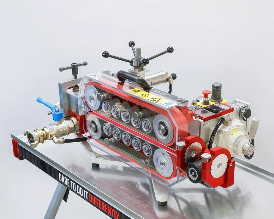
When using a railway cable-laying machine to lay fiber cable or pipe in the ground, the scope of design work is significantly reduced, as there is no need to carefully determine the route for cable laying. The cable installation process becomes significantly faster and more efficient. However, laying optic cable with a railway cable-laying machine on active railway tracks requires designated maintenance windows in train operations, which complicates the operation of both the cable line and the railway track.

Pic 2. Railway cable-laying machine
Cable laying under the embankment is allowed only in subgrade consisting of draining soils (stone, pebbles, gravel, coarse- and medium-grained sands).
On electrified sections, a minimum clearance of 0.5 m must be maintained between the poles and the cable installed along the railway embankment. If the distance is less than 0.5 m, the cable must be placed in asbestos-cement or protective polyethylene pipes (PPE) over a length of 3 m on both sides of the pole.
It is allowed to use pipes cut along the longitudinal axis for laying cables inside them, followed by their sealing.
Obstacle crossings
River crossing
When crossing a river, its characteristics must be taken into account. If the river is navigable or wider than 300 meters, the cable trunk line design must provide redundancy for each trunk cable – one cable is installed on the bridge, and the other runs along the riverbed.

Pic 3. River crossing HDD diagram
Laying fiber cables on railway bridges is carried out in special troughs or protective conduits made of fire-resistant materials that do not propagate combustion. At the same time, protection of the cable against mechanical damage must be ensured.
Railway Crossings
Railway crossings are typically constructed using trenchless installation methods – laying fiber optic cables using a horizontal directional drilling (HDD) rig.

Pic 4. Railway crossing HDD diagram
In some cases crossings over minor railway lines may also be carried out using the open-cut method after obtaining approval from the owners of these structures.
Aerial fiber deployment on railway contact network poles
The NESC standard defines the requirements for installing self-supporting fiber optic cables on railway electrification poles with voltages above 1000 V and defines the basic principles of safe installation practices for suspending fiber cable. The standard also establishes requirements for the attachment of self-supporting optic fiber cables on bridges and in tunnels.
This standard is intended for personnel involved in the design, construction, installation, maintenance, and repair of fiber optic communication lines on the railway infrastructure.

Pic 5. Fiber cable over a railway bridge
On electrified sections of railways, fiber optic cables with a jacket made of tracking-resistant material should be used.
Three stages of aerial fiber optic cable installation
Stage 1
Installation of brackets on poles and pulling of the pilot rope. When installing brackets, there should be no height difference between adjacent brackets.
The pilot rope can be pulled in two ways. Manually – a person pulls the dielectric pilot rope, moving sequentially from pole to pole. Or using a railway car equipped with a lifting mechanism and a winch.
Stage 2
Rolling the cable. Cable drum is installed at one end of the span. A pin (solid metal shaft) is inserted into it, and the pin itself is mounted on cable trestles. The cable is attached to the end of the rope using a cable sleeve. A winch is installed at the other end of the span, onto which a dielectric leader cable is winded. After the winch, the cable is winded onto an empty spool for winding. After starting the winch, the dielectric pilot rope is winded onto the empty spool. The cable should be pulled at a speed of approximately 0.5 m/s.
Cable winding is stopped at 15 meters from the winch. On the drum side, the cable is attached to a pole. The cable is then secured at one end, and the required design sag is adjusted. Once the sag is set, the cable is attached to the pole on the winch side.
Stage 3
The temporary stringing rollers are replaced with permanent cable clamps. The rollers are removed from the brackets, and holders are installed in their place to secure the optic cable.
Installation of splice closures
When attaching aerial fiber cable on contact network poles, splice closures are installed on the poles at a distance of 6.5 meters from the ground. A 15–30 meter slack loop is provided on each side of the splice closure.
When laying buried fiber cables in PP pipes, splice closures are placed in fiber chambers / manholes. A 10 m slack loop is provided on each side of the splice closure.

Pic 6. Fiber chamber / manhole

Written by Vasiliy Grodetskiy | CTO of Splice.me
With over 20 years of experience in fiber network engineering, Vasiliy has been directly involved in the evolution and deployment of fiber infrastructure worldwide. Vasiliy brings deep expertise in industry standards, regulatory environments, and the practical trade-offs between different approaches to fiber network roll-out.