When it comes to the quality of fiber network design documentation, the most pressing issues are in the area of designing aerial (overhead) fiber-optic lines using ADSS (All-Dielectric Self-Supporting), OPPC (Optical Fiber Composite Phase), OPGW (Optical Ground Wire) cables on high-voltage power lines.
Problem field
- The quality of the optical cable itself, couplings, clamps, and other components used.
- The quality of the design, calculations, and design solutions used.
- The quality of construction and installation work.
Let’s look at the issues of the quality of network documentation when designing overhead fiber networks with ADSS and OPGW on high-voltage power lines.
Our database of fiber optic cable failure statistics during operation shows that up to half of all accidents during operation are associated with the low quality of the design solutions, which lead to a sharp increase in operating costs for maintaining the fiber line in a standard condition, the need for emergency repair work, and a decrease in the quality of services provided to customers. Thus, the desire to reduce capital costs, including design costs, can result in much higher operating costs.
Regulatory framework
One of the most common comments on project documentation is the use of outdated regulatory documents, such as obsolete rules for “the design, construction, and operation of fiber-optic communication lines”.
Often, the project author refers to both the requirements of current regulatory documents and invalid versions to implement the project solution despite existing limitations.
Currently, the main document for the design of aerial fiber optic communication lines is NESC, and it is mandatory for organizations engaged in the design, construction, and operation of fiber optic networks on power lines. Current edition of NESC takes into account the current regulatory framework and combines, standardizes, and unifies the mandatory and basic requirements for the design of fiber optic lines.
Read more on this topic: Standards and regulations in FTTH networks
Materials used
When selecting fiber cables and fiber optic cable components, designers must take into account the current level of technology, analyze the current state of the industry, and apply the latest technical solutions.
The history of commercial fiber spans less than half a century, and modern fibers are radically different even from those that were common 20 years ago. So it’s unacceptable for a project to impose requirements on fiber, even of the G.652B category, which arise from copying and pasting from old projects.
Modern G.652D standard fibers with reduced attenuation and increased bend resistance at the same price have undeniable advantages in operation: a larger optical budget allows for increased power reserve, more connections and branches, and a greater number of repairs. Reducing the risk of increased attenuation from unintentional bends leads to a significant increase in line reliability. Also, when designing, and all other things being equal, it is necessary to choose an optical cable with improved characteristics (for example, with increased and excessive temperature range), which significantly increases the available construction season for the contractor, making it practically year-round, and also indicates the use of high-quality polyethylene for the optical cable sheath, which retains its properties over a wide temperature range.
This is by no means a complete list of aspects that designers need to pay attention to when determining the requirements for materials and equipment used in design. In this case, an important factor for the design organization is the ability to quickly obtain complete and up-to-date information from manufacturers.
Cable clamps
- Squeezing of the fiber cable with an increase in optical fiber attenuation in clamps that are not suitable;
- Cable sagging to the ground due to the use of clamps with a larger diameter than the cable (resulting in the cable slipping in the clamps);
- Damage to the cable sheath due to the use of clamps with a clamping force lower than the permitted load on the cable.
- The types or brands of clamps for aerial cable must be recommended for use by the cable manufacturer;
- The cable diameter must fit exactly within the permitted range of clamp sizes;
- The fastening strength of the cable in the tension clamps must be at least 90% of the cable’s breaking strength (RBS).
Impact of the power line electric field
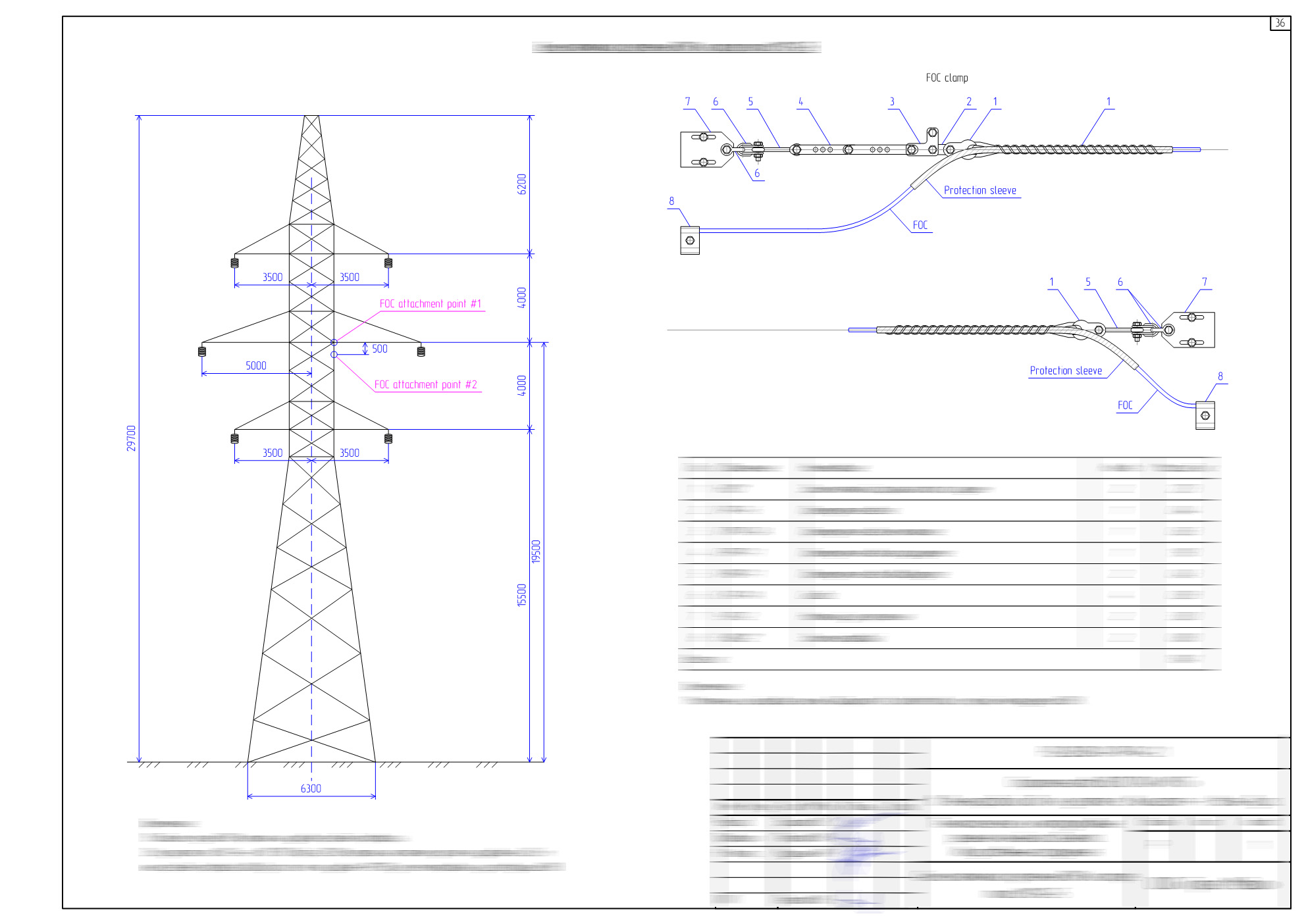
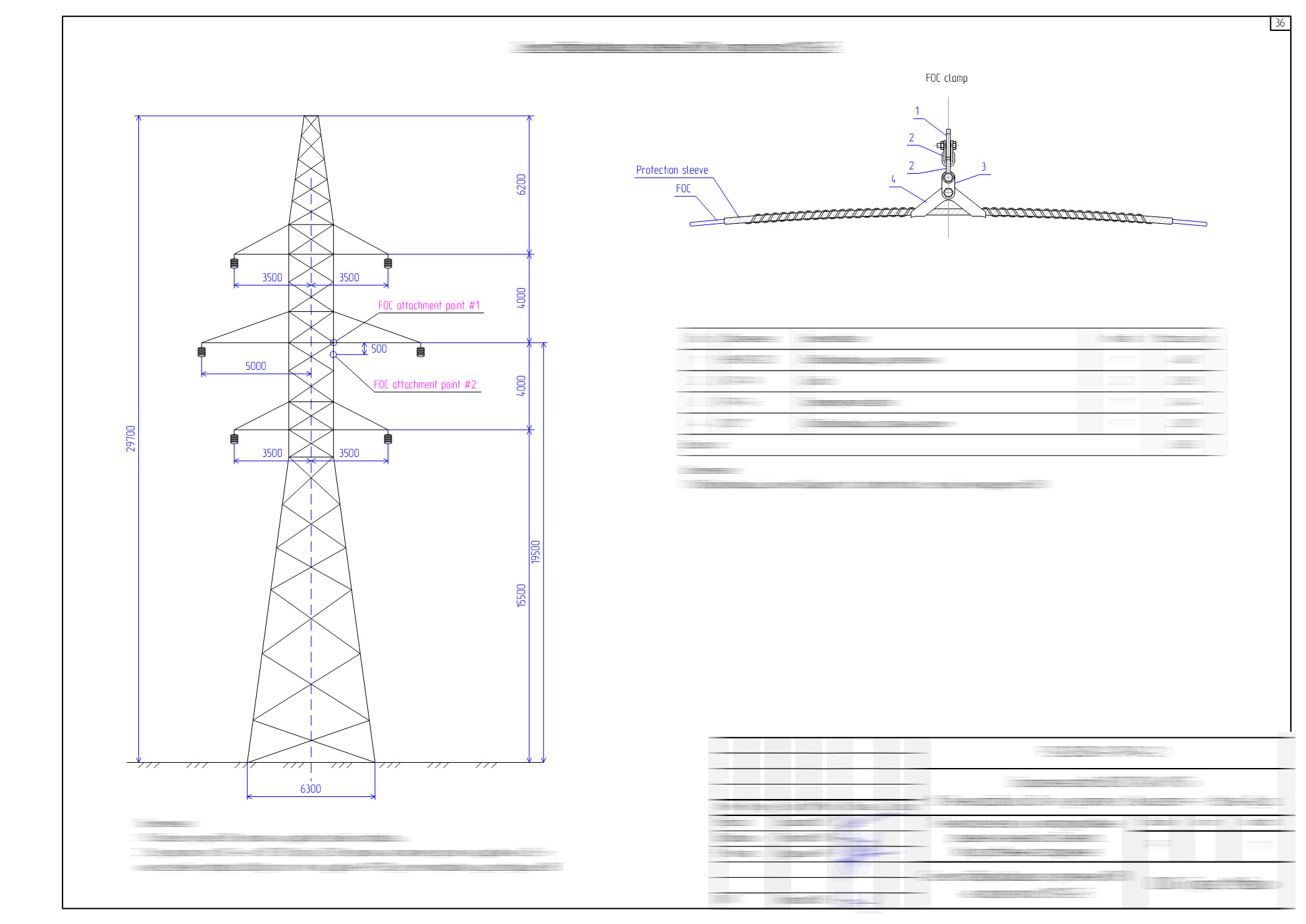
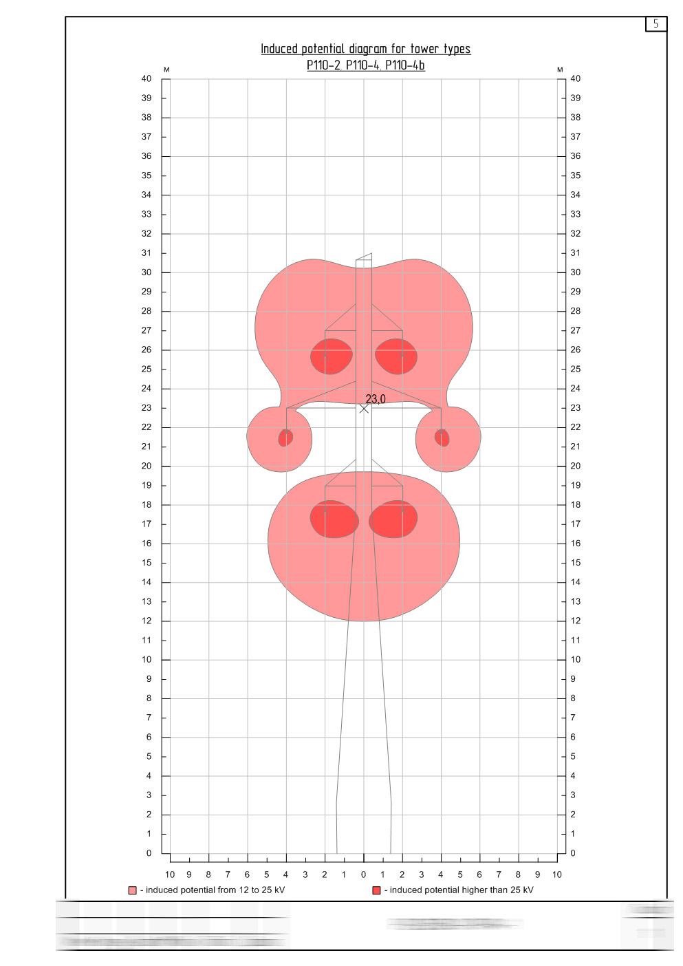
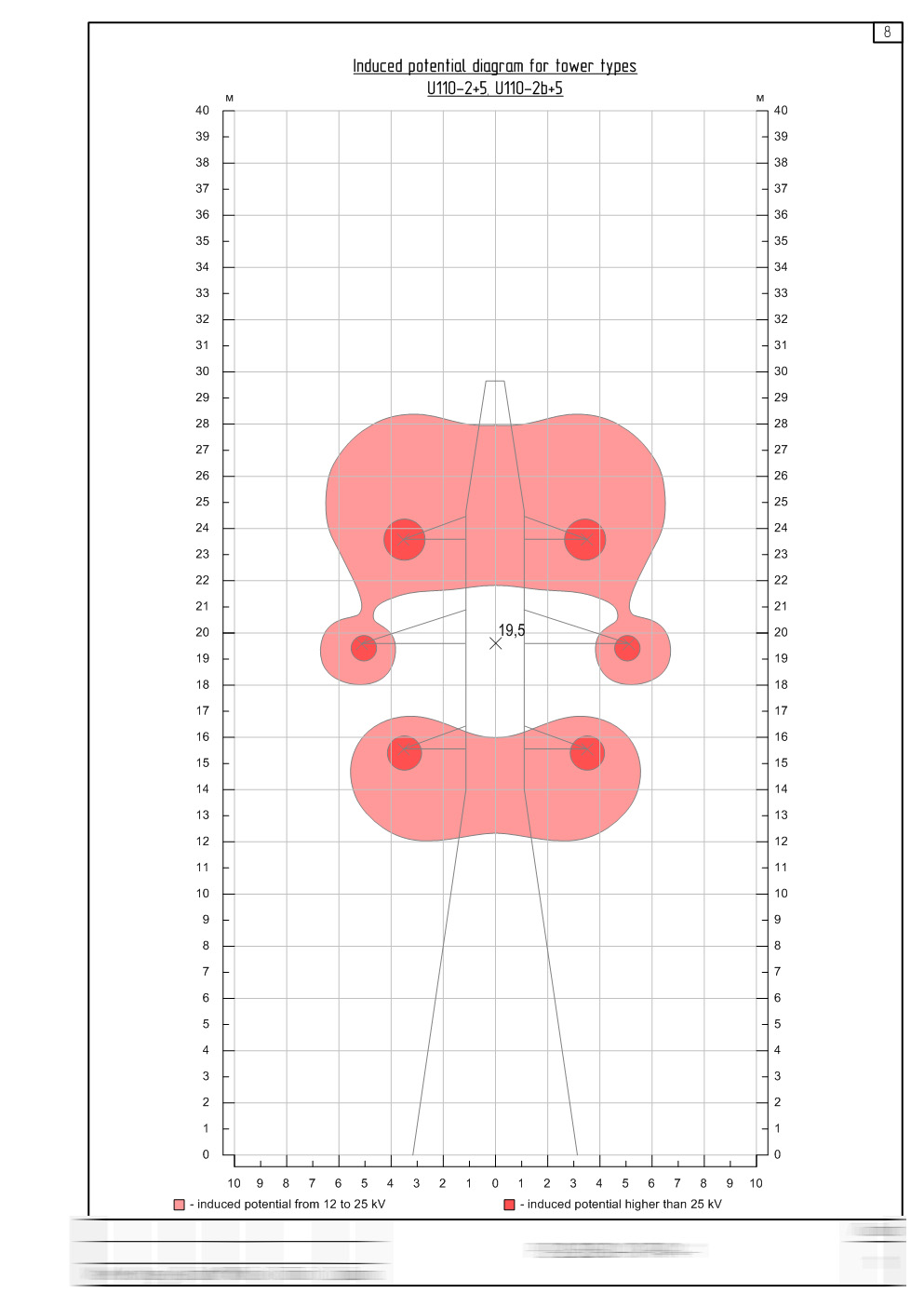
Fiber optic communication lines on 110 kV and above power lines should be organized using OPGW (optical ground wire). However, in cases where its suspension is not possible, ADSS fiber cables are often used. In this case, it is critically important to place the ADSS suspension point in the area with the least electric field potential.
Neglecting electric field calculation during design or performing it formally may lead to possible electrothermal degradation of the optical cable, which occurs from partial arc discharges from the ends of the clamps to the contaminated fiber cable sheath. Deterioration of the sheath leads to the failure of the optical cable, up to its breakage and the impossibility of further operation.
Mechanical calculations
Another critically important design element is the mechanical calculation of pole loading and cable sag. Ice and wind loads that occur during operation must be taken into account in the calculations so as not to exceed the permissible tensile loads of the cables, as well as to maintain the necessary ground clearance.
A formal approach to this part of the design documentation can lead to:- Improper fiber cable tension during installation, which will significantly reduce its service life span;
- Selecting a fiber cable with an improper RBS, which will lead to cable failure in harsh climatic conditions;
- Non-compliance with ground clearance around intersections, for example, roads, and, consequently, possible cable breakage by passing vehicles.
In the majority of cases, software products and automated design systems intended for conductors, rather than optical cables, are used. The theory of calculations for fiber cables differs from the theory of calculating conductors, especially in terms of elasticity modules – finite and elongation ones.
For example, the cross-section ‘by elements’ is not necessary or a fiber cable – as a rule, elasticity modules are given in relation to the total cross-section of the cable, in contrast to conductors, where loads and strengths are calculated based on the pure cross-section of the metal and its elasticity modules.
Also, we don’t recommend making calculations using the reduced span method: the unevenness of the heights and lengths of the spans has a strong influence on the calculation of the sag of conductors and fiber cables. In this case, the sag of overhead spans must be determined for each span under various load cases to comply with clearance and insulation distances.
Convergence of fiber cables with power line elements in case of galloping
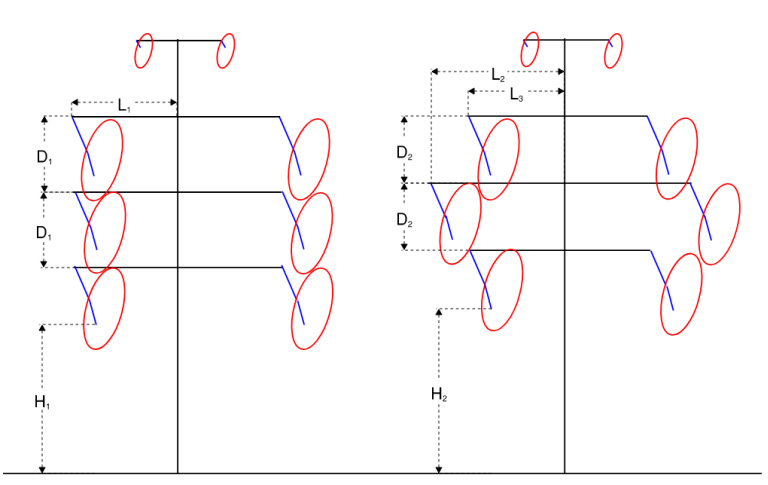
Galloping is one of the most dangerous types of threats associated with wind-induced vibrations of power line elements and aerial fiber cable plants. The most common and most dangerous cases are those that involve one-sided deposits in the form of wet snow, ice, or frost at transverse wind speeds of 15 to 60 mph.
Available data show that up to 90% of galloping cases lead to disruption of the power line operation or damage to its elements, with only 30% of cases limited to short-term power line outages and not accompanied by interruptions in the operation of lines lasting from several hours to several days. In some cases, repair and restoration work require significant costs and prolonged line outages. In this regard, an important part of the design documentation is also the calculation of compliance with the minimum permissible distances between the ellipses of the fiber cable galloping and the ellipses of the phase wires.
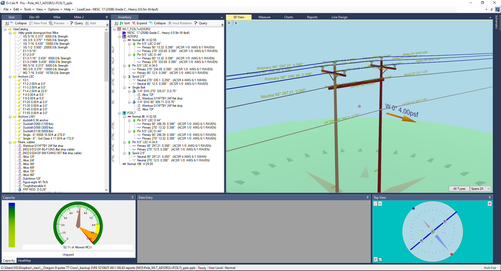
Pole loading analysis
Fiber cable is an additional element of the overhead line, which increases the loads on poles, towers, and pylons. If the design documentation does not include a calculation of allowable loads on poles, this may lead not only to the failure of the communication line during operation, but also to an emergency on the power line, interruptions in power supply, and lengthy and costly repairs.
In this regard, when designing overhead fiber cables on power lines, it is necessary to determine the total loads on support structures from all phase wires, lightning protection conductors, and fiber cables, taking into account wind loads and ice deposits, and compare them with the allowable loads. If the allowable loads are exceeded, it is recommended to reinforce the supports, foundations, or ground fastenings, replace the supports, or reduce the spans by installing additional poles.
Read more on this topic: Fiber network splicing and utility pole loading analysis
Thermal impact of short-circuits on OPGW
The need for a detailed calculation of the processes occurring in lightning protection cable during short circuits is dictated by serious problems arising in the operation of power lines and associated with current spreading, which is accompanied by damage to high-voltage line elements. Sometimes, galvanized lightning protection cables with small cross-sections on existing overhead lines do not provide the required level of thermal resistance, which leads to repairs. Lightning protection cables, including ones with built-in fiber cable, based on a combination of aluminum-clad steel wire and aluminum alloy wires, have high resistance to short-circuits.
At the same time, it is important to identify sections of power lines with an increased level of thermal impact of short-circuits on the lightning protection cable. In most cases, the greatest thermal impact is around the substations. However, there may also be cases where the maximum thermal impact occurs far from the substation due to an increase in the shutdown time. All this requires calculation of many options using lightning arresters of different cross-sections and specific resistance in different sections of the power line. It is necessary to ensure high accuracy of calculations, since in the case of thermal instability of the OPGW, among other factors, there is a risk of link loss.
In addition, the optimal calculation of the required characteristics of the lightning arrester in terms of resistance to short-circuits using different OPGW cables in separate sections leads to savings in costs, in contrast to the “head-on” approach, when one type of OPGW with maximum thermal stability is used along the entire line.
Conclusion
- Taking into account all the requirements of up to date regulatory documentation
- Implementing the latest developments in materials and equipment
- Performing all necessary calculations and checks
- Reduced number of emergencies
- Increased fiber line or network life span
- Significant reduction in operating costs
Take care of your splice sheets
1000+ ISPs are already saving weeks of work with Splice.me!