When testing a PON network, operators are typically concerned with two main issues:
- The actual attenuation in the optical link between the central node and the subscriber device (whether currently active or being prepared for connection).
- The location of the problematic section if the actual attenuation in the line turns out to be higher than expected (calculated or reference).
To answer the first question, it is sufficient to perform simple measurements using an optical tester. The second question is more complex and requires the use of an optical time-domain reflectometer (OTDR), as well as some experience in interpreting reflectograms.
As a rule, it is desirable that all necessary measurements be performed on an operational PON network without disconnecting subscribers (except, perhaps, the one being tested). Such testing is performed at a non-operational wavelength using additional devices (DWDM wavelength multiplexers, filters) to ensure that the radiation from the measuring equipment does not interfere with the useful signal. As previously mentioned, in a PON network, the 1490 or 1550 nm wavelength (for video) is used for the downstream channel (from the central office to subscribers), and 1310 nm for the upstream channel. The 1625 nm wavelength is typically used for testing PON networks.
The light emitted by the test equipment (tester, reflectometer) is injected into the fiber right after the OLT using a wavelength multiplexer (DWDM). This light can cause interference at the optical receiver of the subscriber device. Therefore, a filter must be installed in front of each ONT. To enable testing without taking the network offline, the wavelength multiplexer and filters must be permanently integrated into the optical path.
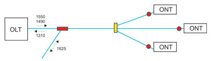
Pic 1. Wavelength multiplexer and filter connection diagram in a PON network.
A 1625 nm optical tester is used to measure attenuation in the optical link between the OLT and the ONT. The tester’s transmitter is connected to the free end of the wavelength multiplexer on the OLT. The tester’s receiver is connected to the free end of the fiber upstream of the filter.
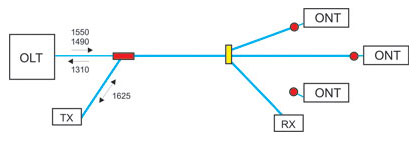
Pic 2. Attenuation measurement with an ONT being disconnected.
Attenuation can be measured without disconnecting the subscriber device. To do this, a wave multiplexer – rather than a filter – must be used on the ONT side, just as on the central node.
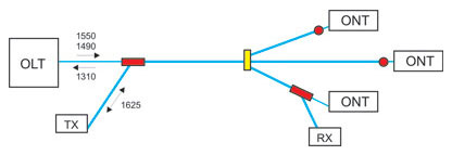
Pic 3. Attenuation measurement without disconnecting ONTs.
Attenuation at 1625 nm is slightly higher than at 1550 and 1490 nm (by an average of 10%). Therefore, testing attenuation at 1625 nm provides an upper bound estimate for attenuation at the operating wavelengths. If this estimate falls within the acceptable budget (~23 dB), then the attenuation at the operating wavelengths is known to meet the budget requirements. If the attenuation at 1625 nm exceeds the acceptable value, then to accurately determine the attenuation at the operating wavelengths, a recalculation based on the optical cable specifications must be performed.
Measuring in a PON network using an optical tester provides the actual attenuation value for the section from the OLT to the ONT, but does not answer the question of where the problem section is located if this attenuation turns out to be higher than expected (calculated or reference). To locate the problematic section, a more sophisticated device is used – an optical time-domain reflectometer (OTDR).
The OTDR, equipped with a 1625 nm test module, is connected to the free end of the wavelength multiplexer on the OLT (see pic 4). The reflectometer’s light signal propagates through the PON tree and, due to reflection off obstacles and backscattering within the optical fiber, partially returns to the reflectometer’s input. Thus, a reflectogram of the PON tree is obtained – a graph of line attenuation as a function of distance. Each peak or spike in attenuation on this graph corresponds to a specific network element or an event in the fiber.

Pic 4. Capturing a reflectogram on a PON network.
The procedure of testing a PON network using a reflectometer is as follows. After each change to the network topology (connecting a new subscriber, replacing a splitter, etc.), a baseline (reference) reflectogram is captured, corresponding to the network’s normal state. If problems are detected in the network (for example, if the attenuation measured by an optical tester is higher than the calculated value), a new reflectogram is recorded and compared to the reference one. New events on the reflectogram pinpoint the location of the problematic section.

Pic 5. New events analysis on a reflectogram.
A reflectometer can be used to monitor a PON network and detect fiber degradation before problems arise. To do this, one should regularly (for example, once a week) capture a network reflectogram and compare it with a baseline reflectogram. If any deviations or, even more so, new events appear on the reflectogram, you must analyze their possible causes and, if necessary, take appropriate preventive measures.
What measurements in FTTx PON/GPON networks should you perform?
During the deployment of FTTx PON networks, four key measurements must be performed:
- unidirectional measurement of losses in the cable sections prior to splicing;
- bidirectional measurement of optical return loss (ORL);
- bidirectional measurement of optical loss between two endpoints;
- bidirectional line characteristics measurement;
- reflectogram measurement of each section of the optical line, including splitters.
During the commissioning of FTTx PON networks, two main measurements must be performed:
- measurement of optical power at the OLT output;
- measurement of optical power of upstream and downstream of the PON network branch when adding each new ONT.
Read also: Challenges in deploying PON networks, a big PON cheat sheet with lots of numbers

Written by Vasiliy Grodetskiy | CTO of Splice.me
With over 20 years of experience in fiber network engineering, Vasiliy has been directly involved in the evolution and deployment of fiber infrastructure worldwide. Vasiliy brings deep expertise in industry standards, regulatory environments, and the practical trade-offs between different approaches to fiber network roll-out.