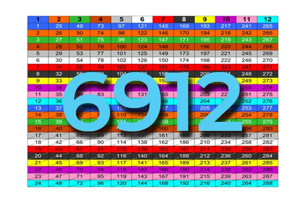
Power ratio in mW and dBm
dB is the ratio of two powers. For example, for the loss (attenuation) in a segment of optical fiber we have the value at the input of the segment and at its output. If we have measured gains in linear units (e.g. in Watts – W), the loss value in dB is calculated by the formula:
Loss (dB) =
10 lg ( mW1 / mW2 )
When both gains are equal, the loss is 0 dB, so there is no loss (doesn’t happen obviously).
If we operate with absolute gains measured in relation to 1 milliwatt (mW), they are expressed in dBm, and are calculated as follows:
Power Level (dBm) = 10 lg ( mW / 1 )
For “household” needs, in order not to calculate mW to dBm and vice versa every time, here’s a ready-made correspondence table:
| Level in dB | Optical Gain, mW | Level in dB | Optical Gain, mW | Level in dB | Optical Gain, mW |
| 0 | 1.0 | 17 | 50.1 | 34 | 2511.9 |
| 1 | 1.3 | 18 | 63.1 | 35 | 3162.3 |
| 2 | 1.6 | 19 | 79.4 | 36 | 3981.1 |
| 3 | 2.0 | 20 | 100.0 | 37 | 5011.9 |
| 4 | 2.5 | 21 | 125.9 | 38 | 6309.6 |
| 5 | 3.2 | 22 | 158.5 | 39 | 7943.3 |
| 6 | 4.0 | 23 | 199.5 | 40 | 10000.0 |
| 7 | 5.0 | 24 | 251.2 | 41 | 12589.3 |
| 8 | 6.3 | 25 | 316.2 | 42 | 15848.9 |
| 9 | 7.9 | 26 | 398.1 | 43 | 19952.6 |
| 10 | 10.0 | 27 | 501.2 | 44 | 25118.9 |
| 11 | 12.6 | 28 | 631.0 | 45 | 31622.8 |
| 12 | 15.8 | 29 | 794.3 | 46 | 39810.7 |
| 13 | 20.0 | 30 | 1000.0 | 47 | 50118.7 |
| 14 | 25.1 | 31 | 1258.9 | 48 | 63095.7 |
| 15 | 31.6 | 32 | 1584.9 | 49 | 79432.8 |
| 16 | 39.8 | 33 | 1995.3 | 50 | 100000.0 |
Uneven splitter ratios and losses
A very frequent question is how the splitter ratio in an optical splitter relates to the actual signal gain. In other words, how much attenuation a splitter contributes to each output. Here’s a table of estimated splitter attenuation characteristics. It should be noted that this table is applicable for fused optical splitters (FBP) and of course does not pretend to absolute accuracy (peculiarity of manufacturing of FBT splitters). It is also worth keeping in mind that the attenuation at the splitter connection, be it a fusion splice or connector, you should take into account yourself.
| Splitter ratio, % | Insertion Loss, dB | ||
| Single-window | Double-window | Triple-window | |
| 50 / 50 | 3,4 / 3,4 | 3,6 / 3,6 | 3,4 |
| 45 / 55 | 3,8 / 2,9 | 4,1 / 3,1 | 3,7/2,7 |
| 40 / 60 | 4,4 / 2,5 | 4,7 / 2,7 | 4,4/2,6 |
| 35 / 65 | 5,0 / 2,2 | 5,3 / 2,4 | 4,8/2,0 |
| 30 / 70 | 5,6 / 1,8 | 6,0 / 1,9 | 5,7/1,9 |
| 25 / 75 | 6,3 / 1,5 | 6,9 / 1,6 | 6,9/1,3 |
| 20 / 80 | 7,4 / 1,2 | 7,9 / 1,3 | 7,6/1,2 |
| 15 / 85 | 8,8 / 0,9 | 10,0 / 0,9 | 8,6/0,7 |
| 10 / 90 | 10,8 / 0,6 | 11,3 / 0,6 | 11,0/0,65 |
| 5 / 95 | 13,8 / 0,4 | 15,2 / 0,45 | 14,2/0,4 |
Even splitter ratios and losses
What happens if the splitter has three or more outputs? Here’s a table with calculated attenuations for even fiber optic splitters with 2 or more outputs.
| Splitter ratio |
Mathematical loss, dB |
Insertion loss, dB |
Total loss, dB |
Connector loss, dB |
Total loss with connector, dB |
| 1 : 2 | -3.01 | -0.8 | -3.81 | -1.2 | -5.01 |
| 1 : 3 | -4.77 | -0.8 | -5.57 | -1.2 | -6.77 |
| 1 : 4 | -6.02 | -0.8 | -6.82 | -1.2 | -8.02 |
| 1 : 5 | -6.99 | -0.8 | -7.79 | -1.2 | -8.99 |
| 1 : 6 | -7.78 | -0.8 | -8.58 | -1.2 | -9.78 |
| 1 : 7 | -8.45 | -0.8 | -9.25 | -1.2 | -10.45 |
| 1 : 8 | -9.03 | -0.8 | -9.83 | -1.2 | -11.03 |
| 1 : 9 | -9.54 | -0.8 | -10.34 | -1.2 | -11.54 |
| 1 : 10 | -10.00 | -0.8 | -10.80 | -1.2 | -12.00 |
| 1 : 11 | -10.41 | -0.8 | -11.21 | -1.2 | -12.41 |
| 1 : 12 | -10.79 | -0.8 | -11.59 | -1.2 | -12.79 |
| 1 : 13 | -11.14 | -0.8 | -11.94 | -1.2 | -13.14 |
| 1 : 14 | -11.46 | -0.8 | -12.26 | -1.2 | -13.46 |
| 1 : 15 | -11.76 | -0.8 | -12.56 | -1.2 | -13.76 |
| 1 : 16 | -12.04 | -0.8 | -12.84 | -1.2 | -14.04 |
| 1 : 17 | -12.30 | -0.8 | -13.10 | -1.2 | -14.30 |
| 1 : 18 | -12.55 | -0.8 | -13.35 | -1.2 | -14.55 |
| 1 : 19 | -12.79 | -0.8 | -13.59 | -1.2 | -14.79 |
| 1 : 20 | -13.01 | -0.8 | -13.81 | -1.2 | -15.01 |
| 1 : 25 | -13.98 | -0.8 | -14.78 | -1.2 | -15.98 |
| 1 : 30 | -14.77 | -0.8 | -15.57 | -1.2 | -16.77 |
| 1 : 32 | -15.05 | -0.8 | -15.85 | -1.2 | -17.05 |
| 1 : 35 | -15.44 | -0.8 | -16.24 | -1.2 | -17.44 |
| 1 : 40 | -16.02 | -0.8 | -16.82 | -1.2 | -18.02 |
| 1 : 45 | -16.53 | -0.8 | -17.33 | -1.2 | -18.53 |
| 1 : 50 | -16.99 | -0.8 | -17.79 | -1.2 | -18.99 |
| 1 : 55 | -17.40 | -0.8 | -18.20 | -1.2 | -19.40 |
| 1 : 60 | -17.78 | -0.8 | -18.58 | -1.2 | -19.78 |
| 1 : 64 | -18.06 | -0.8 | -18.86 | -1.2 | -20.06 |
If you don’t have this table at hand, use this primitive formula to calculate the maximum allowable insertion loss for an optical splitter used in a PON system:
1×N optical splitter (dB) = 0.8 + 3.4 * log2(N)
2×N optical splitter (dB) = 1.0 + 3.4 * log2(N)
Note: ‘N’ denotes the number of outputs.
Learn more about PON
1. Everything about PON design and managing
2. PON: The secret of effective investment
Take care of your splice sheets
1000+ ISPs are already saving weeks of work with Splice.me!