Passive Optical Networks (PON) have become the backbone of high-speed fiber-to-the-home (FTTH) solutions. Network designers and ISPs aiming for efficiency must focus on effective passive optical network design, with careful consideration of PON architecture planning and splitter placement. This guide explores the key components of a robust PON and offers insights into best practices for PON splitter design, ODN design, and PON network management.
What is PON design?
A passive optical network is a fiber-based network architecture that uses unpowered (passive) splitters to enable a single optical fiber to serve multiple endpoints. It means that the only powered (active) equipment is at the service provider’s central unit and on the user’s side. With this approach the whole network in between does not depend on electricity as a factor of possible faults. The design phase plays a critical role in determining efficiency of the network.
Key PON components include:- Optical Line Terminal (OLT) – typically located at the central office
- Optical Network Units/Terminals (ONU/ONT) – at user premises
- Optical Distribution Network (ODN) – the physical infrastructure including fiber cables and optical splitters
While seemingly primitive in the amount of different components, such networks can be designed in many different ways. And there’s enough room for all sorts of errors and inaccuracies. The correct PON network design not only considers a thoughtful equipment placement, but also ensures optimal signal strength and signal balancing across the network, all while controlling costs.
Difference in GPON vs GEPON network design
Before diving deeper, it’s important to distinguish between GPON (Gigabit PON) and GEPON (Gigabit Ethernet PON):
| Feature | GPON | GEPON |
| Standard | ITU-T G.984 | IEEE 802.3ah |
| Downstream Rate | 2.5 Gbps | 1.25 Gbps |
| Upstream Rate | 1.25 Gbps | 1.25 Gbps |
| Efficiency | More bandwidth-efficient (due to GEM framing) |
Lower (Ethernet framing) |
| Split Ratio | Typically 1:64 | Typically 1:32 |
The key is paying extra attention to equipment characteristics, especially min and max signal gains for both OLTs and ONTs. According to this and other factors one defines the physical and logical structure of the network. Also important not to mix up GPON and GEPON equipment!
Optical Distribution Network (ODN) design
ODN design refers to the layout and infrastructure of the fiber path from the OLT to each subscriber. It includes everything a fiber network usually includes:
- Fiber cables from the central unit to some intermediate network points
- Set of intermediate network points – closures, pedestals, etc, of different hierarchy
- Distribution fiber cables between intermediate and access points
- Drop fiber cables from access point to end-users
Good optical distribution network (ODN) design ensures low signal attenuation and evenly distributed optical budget in network branches. Good ODN means it has clear hierarchy. And the points of the network are easily accessible for maintenance while being safe and secure.
GPON splitter design and placement strategy
Splitters are crucial to PON splitter design and have a significant impact on signal gain and overall performance.
Splitter placement strategy – centralized vs distributed
- Centralized splitters are typically installed in the central office. Easier to manage but require much more fibers to get the signal to all users. Can be beneficial in situations, when the provider has nowhere to place the intermediate or access points, e.g. when all available physical fiber paths are in conduits with no cable wells.
- All splitter arrays can be theoretically installed in a building where subscribers are situated, and be fed by a single fiber straight from the central unit. Such strategy also can be called centralized. The advantage is the maximum fiber count economy, disadvantage – the need to travel for maintenance every time.
- Distributed splitters are placed hierarchically closer to subscribers, making the network physically balanced and more survivable, reducing fiber spend, but increasing field maintenance complexity.
Best practices for PON splitter placement
- Avoid 1-cascade network architecture.
- Use 2- and 3-cascades network architecture
- Assume 1:4 or 1:8 splitters in the network’s central unit, use calculated splitters in intermediate and access points.
- Avoid placing splitters in hard-to-reach areas.
- Assume some excessive number of splitter outputs for future upgrades.
- Use PON-specific splice closures, boxes and stuff.
GPON network management tools & techniques
- OLT & ONU monitoring through network management and network monitoring software.
- Bandwidth allocation via DBA (dynamic bandwidth allocation).
- Keeping detailed PON network maps and PON network splice diagrams and records readable, understandable and up to date.
- Fault detection using VFL, OTDR, and SNMP alerts.
- Firmware upgrades and remote provisioning.
How to design a PON network
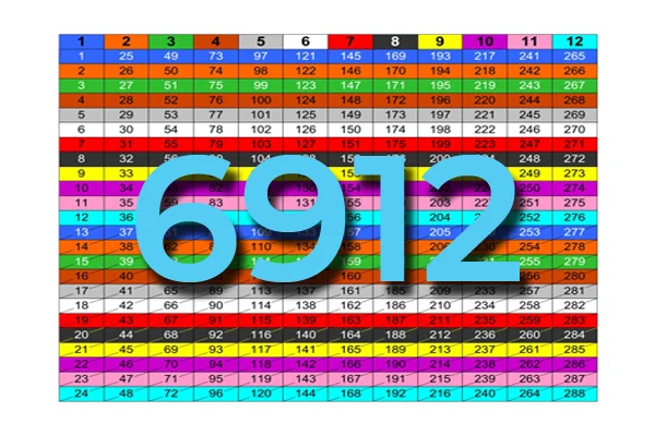
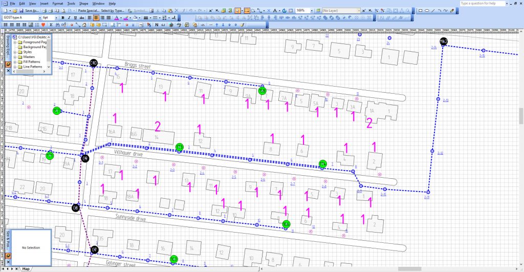
Problems will start straight from the beginning. First, you’ll never encounter a network cluster with 32 potential subscribers. Or a street with exactly 8 households. It will always be a game of assumptions. But assuming you have a strictly outlined coverage area of your future PON network in a city, a way to do it is firstly denote the number of subscribers. This still applies to rural PON network design approach, you will see why. Now when you are looking not at houses with subscribers, but at the amounts of subscribers, you can start encircling them into groups of 8s, 16s, 32s, etc. according to preferable splitting ratios and network hierarchy.
In this picture you see amounts of potential subscribers in each house nicely align into clusters of 32 subscriber per cluster. It means you can assign 1 fiber per cluster, use a 1×4 splitter to get fibers to each house, and use one 1×8 splitter inside a house.
The cluster on the the bottom, where we have 2 houses with 4 subscribers, will make you think, should I:
– Place a 1×8 splitter in the house with 4 subs, and get other 4 fibers to the next house?
– Place a 1×2 splitter and 1×4 splitter in the first house and get 1 fiber to the next house?
– Or maybe place 1×32 splitter somewhere in the center of the cluster?
– Or maybe place two 1×16 splitters in the cluster?
– Or do it in some different way?
The problem is not the amount of solutions, all seemingly equally feasible. The problem is you always get houses with different amount of subs, and they will always be under or over suitable splitting ratios. No problem when there are 30 subs in a cluster – leaving two extra ports of a splitter unoccupied is even better – some reserved ports for unaccounted users is great. But what to do when you get 34 subs in a cluster? Or 45? Break into 2 clusters with too much reserve? Break into many pieces and merge pieces with other clusters? Making this decisions is the quintessence of PON network design.
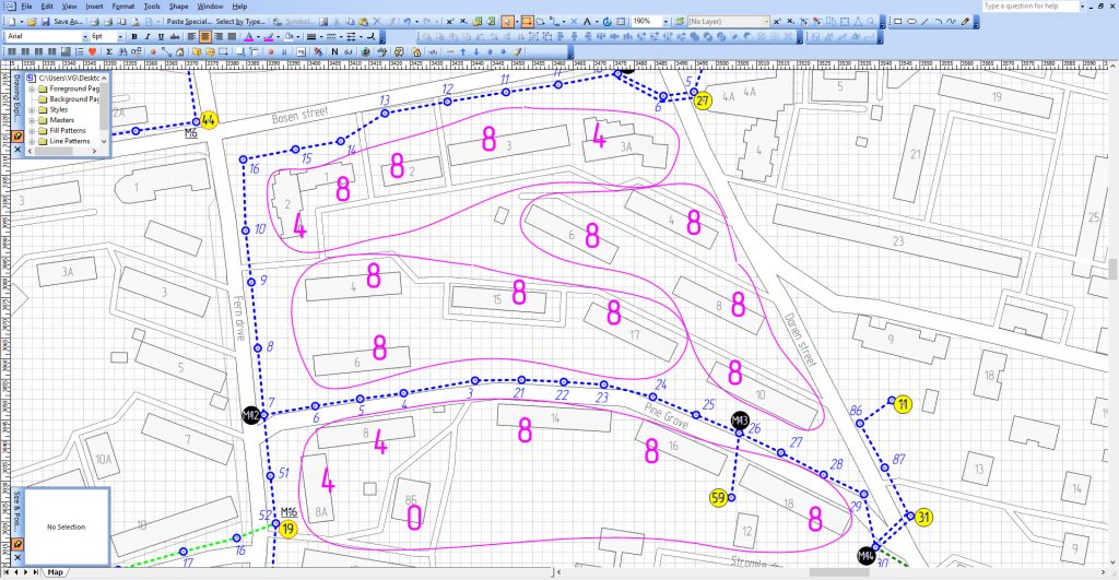
Now let’s get back to a rural PON design. Let’s look at our map.
How would you group those households into groups of 8s? Or maybe 16s? Nothing works!
The way to do it is to break the network into smaller groups, e.g. of 4 houses, and then group those mini-clusters into clusters. Like that:
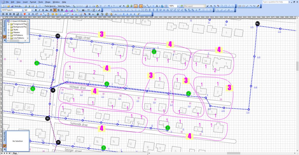
The next problem is you get 10 mini-clusters here. How do you unite them?
– Use one 1×16 splitter to feed all of them and leave 6 ports unoccupied?
– Use an array of smaller splitters to leave less outputs unoccupied?
– Try to group it with other clusters in the adjacent neighborhood?
– Use one 1×4 and one 1×8 splitter but leave the branches of the network with an unbalanced signal gain?
There are plenty of ways to solve this problems. If you are somehow lost – use a chess rule, which says – if you’ve found a great move, look for a better one.
Documenting splicing in a PON network
When it comes to making PON network splicing diagrams, using tools like autocad, coreldraw, visio, draw.io or other generic tools can be a big pita! Way to go is using a specialized tool SPLICE.ME, which helps making them literally in seconds. For example a PON access point with two fiber taps and two 1×4 splitters, schematically looking like this:

– takes only 30 seconds to make in SPLICE.ME and it looks as follows:

Splice.me interface
Learn more about PON
1. PON crib: splitters, ratios, gains, losses
2. PON: The secret of effective investment
Take care of your splice sheets
1000+ ISPs are already saving weeks of work with Splice.me!