Documentation upkeep
Network documentation upkeep
Documentation development and templates
What does ChatGPT say?
Splice.me vs The World
As well as in any other industry, keeping fiber optic network documentation in one place, keeping it easily accessible and up to date is critical for troubleshooting, maintenance, audits, expansions, etc.
Documentation Upkeep
The problem of storing technical documentation is more extensive than it seems and dates back to the middle ages. It is a unique case of documentation storage in general and includes issues of both paper and electronic documentation. Most countries have well-developed systems of legal documents that establish rules and methods for retaining records. Our documentation related to fiber-optic networks is no exception.
There are simple principles that seem too obvious, yet many companies neglect them today.
1. Not keeping documents
Of all the mistakes organizations can make, the first and perhaps the most fatal is ignoring the need to accurately archive and preserve documentation.
2. Retaining all documents, regardless of retention period
The second mistake is keeping all documents, regardless of their retention period. Haphazardly storing documentation, regardless of its real value to the company or retention period, leads to an unnecessary burden on storage facilities, both physical and electronic. It also creates confusion and makes it difficult to find the information you need.
3. Not keeping records of documents
Failure to keep track of documents is a mistake that can lead to serious inconvenience. It’s important to realize that merely keeping paper and electronic documents is not enough. You also need to know where the right documents are located, how long to keep them, and what information they contain.
4. Careless filing
A case is a document or group of files on one issue, united under one cover with a single retention period. Cases are organized by subject matter. Combining files with different retention periods into a single file, or excessive design, can create chaos in the archive and make recording and searching difficult.
5. Not maintaining an archive of electronic documents
With the development of digital technologies and the shift to electronic document management, failing to keep track of electronic records can lead to significant problems. Companies often focus on organizing paper document storage, forgetting about the value of systematizing and recording electronic versions. Insufficient recordkeeping of digital documents can result in the loss of information, hinder the search for and access to necessary documentation, and cause problems during inspections or disputes.
Network documentation upkeep
Now, let’s return to the documentation on fiber optic networks. It can be divided into several types:
- Technical documentation containing information about the technical aspects of the network.
- Work & labour documentation, which reflects the organization and execution of work on the network. This includes documents on the operator’s relations with contractors.
- Financial and legal documentation, including initial authorization documents and documents on the operator’s relations with customers or subscribers.
Technical documentation may include various sections, such as fiber network maps, mathematical calculations of fiber network parameters, equipment and material specifications, books of quantities. These sections are unified to some extent. There are many development tools and computer-aided design systems specifically for it. Some are better and more expensive, while others are worse and free of charge. We know how all this is being stored: in the form of sketches, paper drawings, and files in various formats, some of which cannot be even opened.
Finally, let’s move on to fiber splice documentation. How is this data produced and stored? There are many ways to develop fiber splice data and drawings. Engineers use AutoCAD, Microsoft Visio, Excel, Word, CorelDraw, LucidChart, Draw.io, and many more. As a result, all fiber splice documentation is different.
There is no strict global regulation on fiber splice documentation should look like. Some countries have such regulations, but they are outdated because the FOCL technology is constantly developing and changing. Even where such regulations exist and are updated, they allow for a wide range of interpretation. Therefore, we can conclude that there is no single standard, which provides this diversity in fiber optic splice documentation.
Documentation development and templates
I think it’s indisputable that no one develops any technical drawings from scratch (unless you’re switching to a new CAD system). Any new fiber optic network drawings are developed using previous solutions and files, automation, template sets and stencils. The same is true when working with fiber splice diagrams (or call it splice case diagrams, or whatever); for example, template sets are useful for optic cable ends. I have such libraries and have been building them up for years. Now, let’s estimate how many optical cable templates are needed to develop splice documentation productively.
Let’s start with the most popular fiber counts: 4, 8, 16, 24, 32, 48, 96, and 144. That’s eight types of cables. Sometimes we’ll have unusual fiber counts: 1, 2, 3, 6, 12, 18, 60, 120 fibers. That’s eight more. When working with backbone networks, we encounter even larger fiber counts in cables: 192, 216, 288, 384, 432, and so on. That’s six more pieces. The total is 22 pieces. These cables are divided into modules (call it tubes, buffers, whatever) with 4, 8, 12, 16, or 24 fibers per module. This gives us about 40 different optical cable templates in total. And all of this is just for one color code, such as TIA-598-C. I work with about ten different color codes, not to mention that different countries often have unique color schemes. Even without them, that’s 40 * 10 = 400 cable templates in my library.
MS Visio offers great automation capabilities for working with templates thanks to its built-in Visual Basic for Applications (VBA) coding. It can simplify your work considerably, but it still takes a lot of time.
This is how it looks in Microsoft Visio:
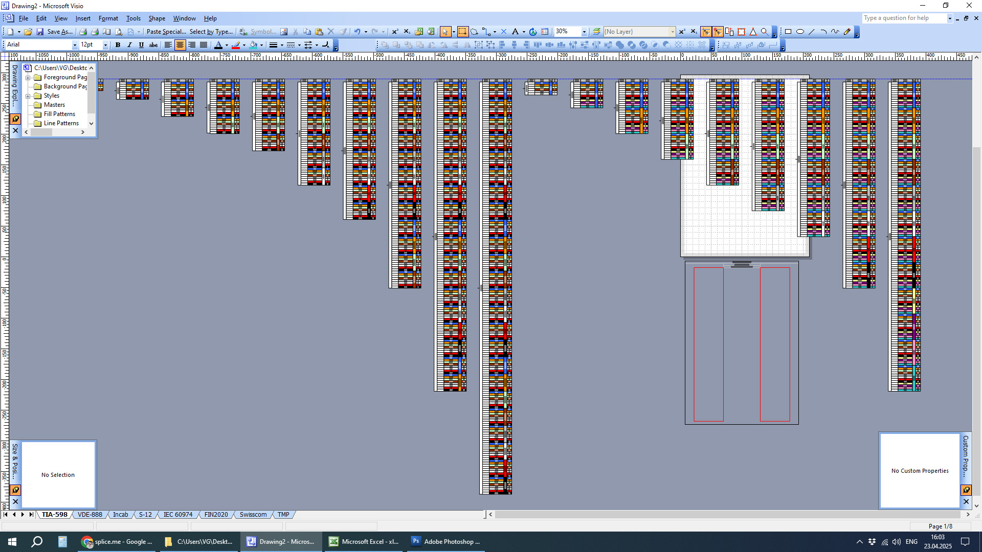
Fiber cable stencil library in MS Visio for TIA-598-C color code
Excel has automation features, but due to its own peculiarities, working with fiber splice matrix is even slower. Even copying and pasting templates can be problematic due to issues with merged cells. You know.
This is how it looks in Microsoft Excel

Fiber cable stencil library in MS Excel
AutoCAD is, of course, the most powerful design software. It is easier to manage templates, but there are far fewer ways to automate the work. Therefore, developing fiber splice documentation and diagrams is also a painful process.

Fiber splicing data in AutoCAD
Whatever general diagram drawing software you use for fiber splicing documentation – it will be constant pain. It will be even more painful when you’ll need to alter those drawings, or add clusters, or visually check fiber paths end-to-end, even print out.
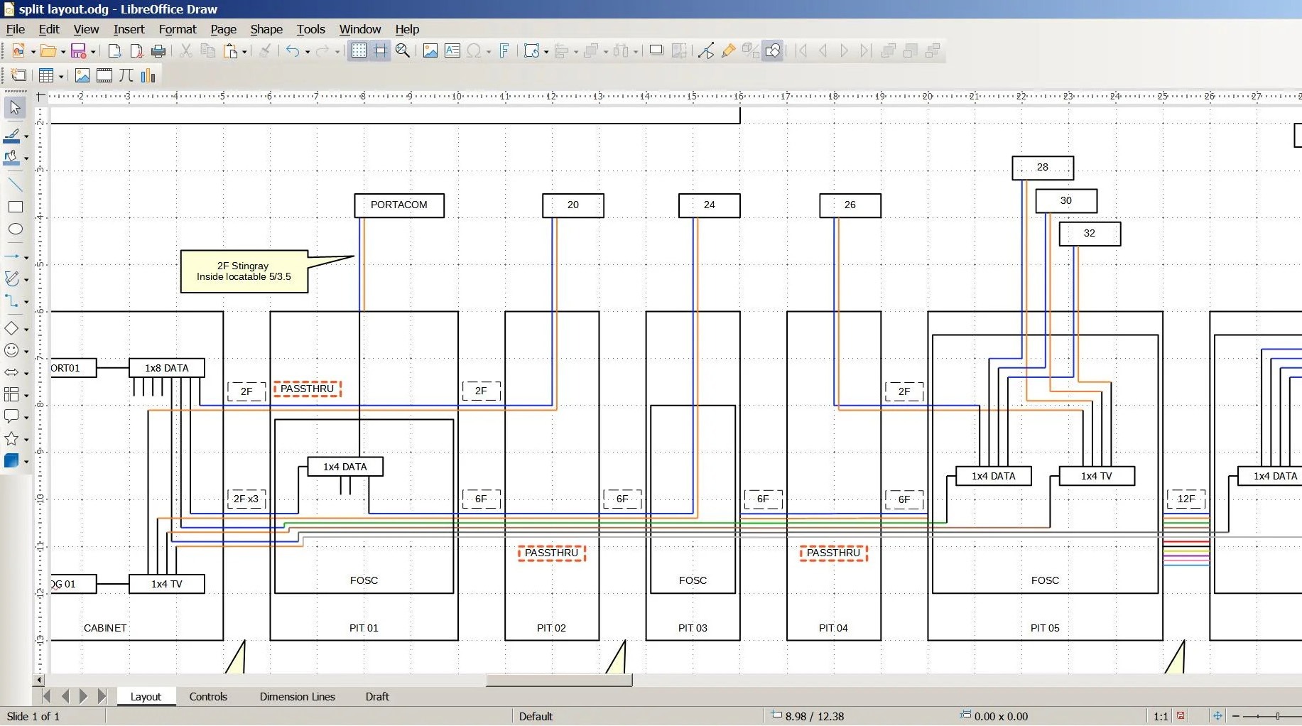
Fiber splicing documentation in LibreOffice Draw
What does ChatGPT say?
Can AI help? I asked him, ‘How can I automate fiber splice scheme drawing and management?’ ‘Great question,’ he replied. Automating fiber splice diagram drawing and management can save a lot of time and reduce human error. Here’s how pros typically do it, and the options available depending on your scale and budget. What follows are his condensed answers:
- Use fiber network management software such as OSPInsight, Vetro, Bentley comms or IQGeo.
- Use a combination of Excel and Visio (what?)
- Visual management in the field: take photos of splice trays and label positions. Store these with GPS location in a cloud folder and use a naming standard so they are easy to reference.
- Build your own Python or JavaScript script that reads fiber routing information from XLS/CSV files and generates a diagram using a library such as Graphviz, D3.js or Matplotlib.
- Other stuff. It also generated a draw.io file as follows:
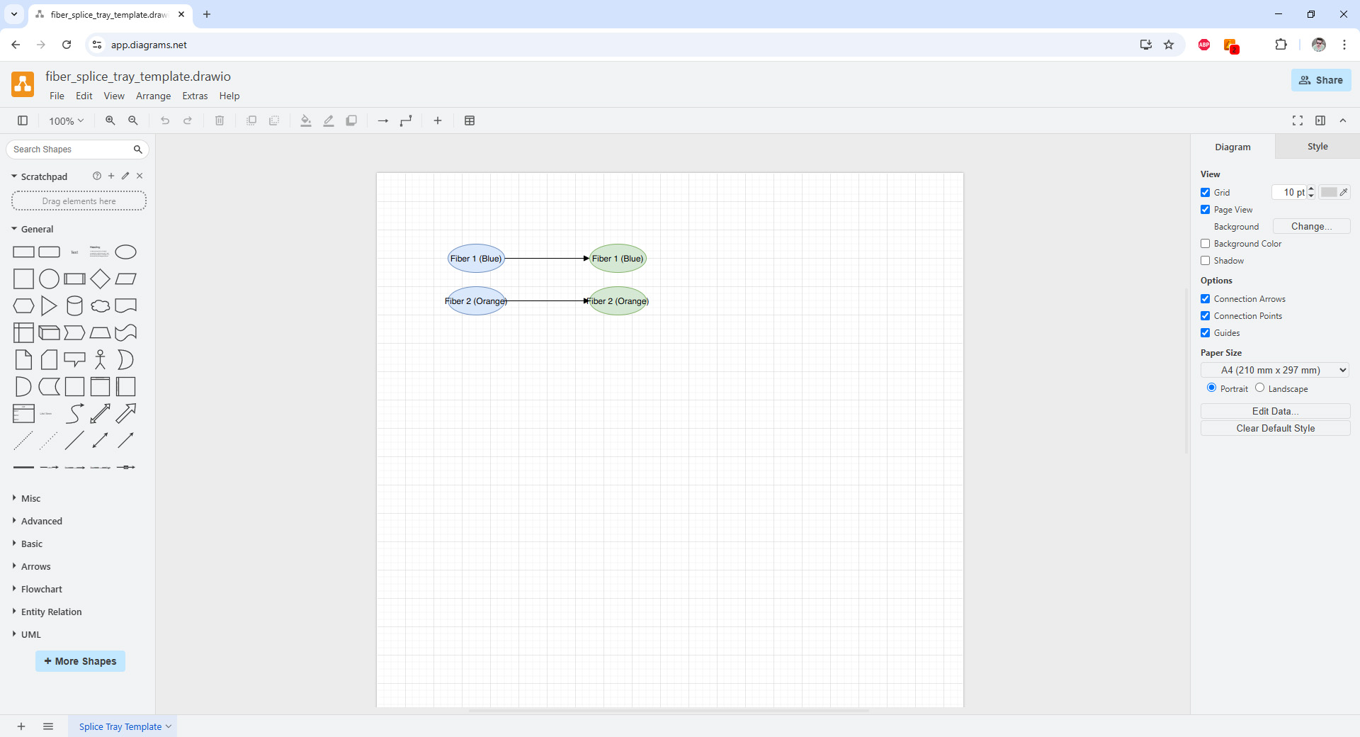
ChatGPT-generated draw.io splice tray template documentation
Splice.me vs The World
How can we simplify all this work? Let’s take another look at our library of 400 fiber optic cable templates. What are the basic parameters of the optical cables? First, of course, is the fiber count. The second most important parameter is how the cable is divided into modules/tubes. The colors of the fibers are defined by a color scheme/code. Can these three parameters accurately determine all fibers, modules, and their colors? It turns out they can. So, can you automate the selection of the template with these three parameters and an “OK” button, spending 4 clicks in total? No, you can only spend 3 clicks if you remove the “OK” button.
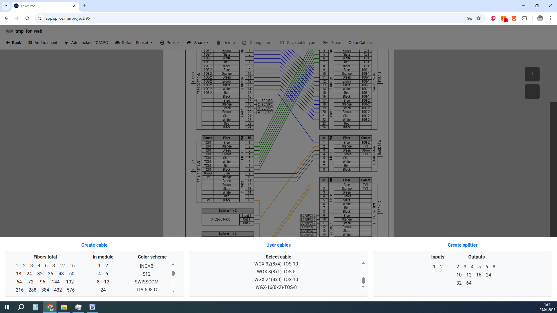
Splice.me fiber optic cable creation menu
If 3 (three) clicks is too many for you, we have a solution! Do the same thing in two clicks. If we can create any cable in 3 clicks, why not save a template to a new library and create it again in just 2 (two)?
Not to mention, cables created this way fit immediately in the right place on the page. There’s no need to agonize over adjusting them. You can also create optical splitters/couplers and other custom equipment the same way. How do I create splices? Exactly the same way, in two clicks.
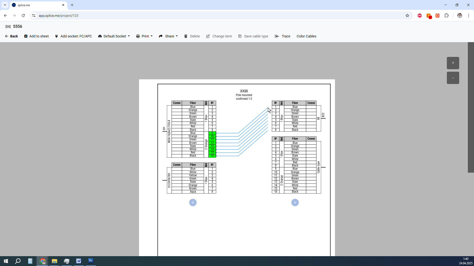
Splice creation on a splice sheet
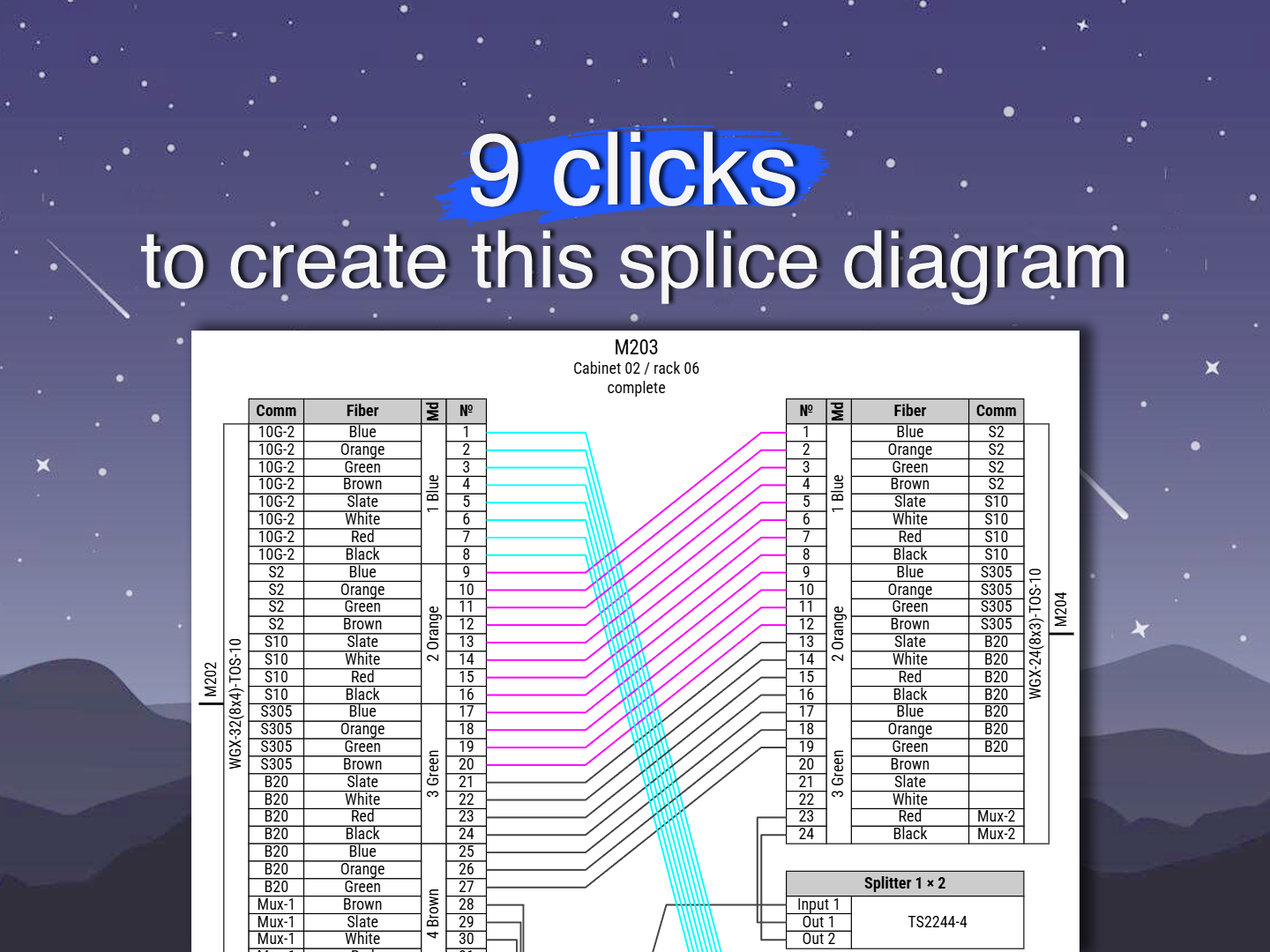
The problem of changes on the sheet is also elegantly solved. Changing splices takes 2 clicks too: select them, drag them out of the cable, and connect them to other fibers. If you need to move cables on the sheet, simply click and drag them to a new location. Just 1 click! This way, you can keep all elements of the fiber splice documentation neatly arranged on the page, maximize the visibility and readability of your diagrams, and ensure uniformity across projects. We would like our approach to designing fiber optic splice diagrams in particular and fiber management in general to become an international standard. Use our application to help us achieve this goal and help attract other users! Because our main mission is to make life easier for network engineers across the world.
Links:
- Understanding the fiber optic network diagram and its relation with splice diagram
- 4 key components of ftth network design – OSP fiber design explained
- Replacing your fiber cable and infrastructure management software or adding Splice.me to your business operations and workflow
- Fiber splice diagram creation platforms – How to streamline fiber optic network management in 2025
- Fiber mapping – how to make a fiber network map
Don't hesitate! Start using splice.me
Create, manage, control all your fiber splicing in one place, fast and easy