Even if you don’t have a suitable software for creating fiber splice sheets, but you know what you are doing and why, you will somehow get things done. You will probably draw the most precise fiber splice sheet even by hand. Problems emerge when there’s no clear understanding of the outcome and the path between some unknown state of the fiber network and a well-documented one.
During my long career dealing with networks I’ve repeatedly faced a variety of the same situations, which altogether led to the appearance of this fiber management system.
Either the whole network is documented in word and excel files, with some network maps in autocad, or even fully on paper. You know, a network was built in the early 2000’s, an engineer grabbed some paper maps, scanned them, drew some fiber paths upon them, and printed them out. If all is good, why change anything? In the 2020s when it comes to network expansion, a contractor receives those paper maps – time to start designing everything from scratch!
Another frequent situation – an old though stable fiber network was built some day by different people. Some splicers documented their work, some did not, some did not care to store the splice schemes or splice reports. When it comes to designing and putting it in order, there are shards of data or just no data at all.
Sometimes service providers create their own software to track, manage, monitor their network and fill it with data for decades. When you try to restore a network map, splicing diagrams, it produces absolute unreadable trash.
But the last straw for me personally was a situation, when my client ISP decided to migrate to s serious network monitoring and automation system, so there was a necessity to input in the whole fiber map and splice all fibers in the system, connect all subscribers, etc. This ISP had some hand drawings for what was going on inside splice closures, but as I found out later, all the splicing was stored inside the chief engineer’s head! So how do you extract it assuming he can’t draw and has no time to draw fiber splice schemes?
Solution – create a template of the whole network of several hundred nodes and subscribers, so the engineer can connect fibers in nodes someway, including a pencil. I did it but after that I gave up.
All next actions were clear.
Now you can:
- create nodes in 1 click
- create fiber cables in 3 clicks
- create optical splitters in 2 clicks
- create many splices in 1 click
This way a cluster of a fiber network of ~50 nodes can be created in ~10 minutes.
Consider it as a way of extracting fiber splicing from your head! When you clearly imagine the contents of a e.g. splice closure in your head, you have only 3 ways of extracting it:
- draw it by hand (fast)
- draw it in some software (slow and painful)
- use splice.me (fast, nice & clean)
I consider splice.me a true fiber management system (FMS). It will not and does not intend to substitute serious network management systems, but it can compliment them on both sides – either when inputting or outputting data, and drastically reduce time expenses when working with splice sheets / splice diagrams.
So as a conclusion – splice.me will help you when you need to
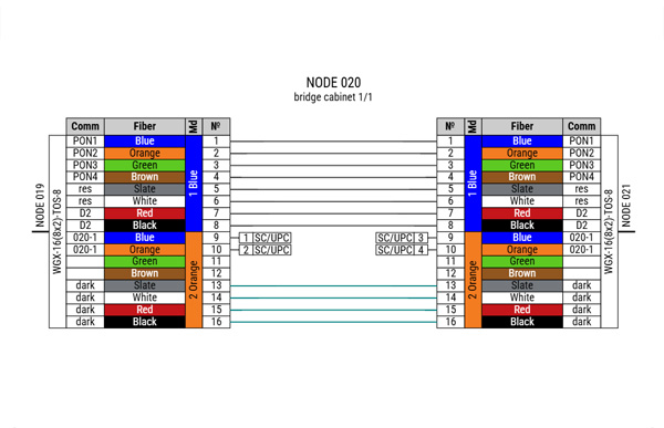
- draw a fiber splice sheet fast
- prove if a splice diagram is doable
- document the network
- migrate to a network management system
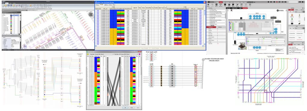
Next time you will be working with gis-based network software, you will still need to peek into some documents describing all fibers. The interfaces are PITA, here are some examples:

That’s where splice.me comes in handy.
Don't hesitate! Start using splice.me
Create, manage, control all your fiber splicing in one place, fast and easy


