Proposed ANSI/TIA-599 v1 “Optical Fiber Splice Diagram Representation Standard”
When designing a fiber optic cable network, many aspects are standardized. However, the appearance of technical drawings is often left to the engineer’s discretion. This is especially true for splice tables. So, which documents can guide their layout?
- ITU-T standards provide general guidance for various cable installations.
- ISO/IEC standards cover identification, labeling, and testing.
- TIA standards define color-coding requirements.
However, none of these offer clear guidance or concrete examples for splice table design. It’s time to create one, turn it into a worldwide standard and a golden rule.
Foreword
This document has been prepared to establish a consistent and interoperable method for the graphical and tabular representation of optical fiber splice information.
Current industry practices vary significantly between network operators, engineering firms, and software systems, resulting in inconsistencies in readability, interoperability, and long-term maintainability of fiber splice documentation.
This standard proposes a unified framework for the creation of fiber splice diagrams to ensure:
- Consistency across systems and organizations
- Compatibility with existing labeling and color coding conventions
- Readability and ease of work for network designers, engineers, splicers, etc.
1. Scope
This document refers to technical drawings of fiber splice sheets, splice schemes, splice tables, splice matrixes, splice charts, splice cut sheets, splice schematics, splice reports, all together called fiber splice diagrams.
This document specifies requirements and recommendations for the structure and representation of fiber splice diagrams used in optical telecommunications networks.
It applies to outside plant (OSP) networks, inside plant fiber distribution systems, splice closures, optical distribution frames (ODF), etc.
This document defines graphical representation rules and minimum information content.
This document does not specify physical installation practices, optical performance requirements, network testing procedures.
This document specifies two separate states of fiber splice diagrams – the sheets and the bedsheets. A sheet depicts splicing within a splice point (node, closure, etc). A bedsheet depicts all splice sheets within a network (cluster, project, etc).
2. Normative References
The following referenced documents are indispensable for the application of this document:
- TIA-598 – Optical Fiber Cable Color Coding
- ISO/IEC 14763-3 – Testing of optical fiber cabling
- ISO 128 – General principles of technical drawings
Where conflicts arise, the requirements of this document shall take precedence for diagram representation.
3. Terms and Definitions
For the purposes of this document:
Fiber – individual optical transmission element within a fiber cable.
Splice – permanent joint between two optical fibers.
Cable face – fiber cable showing all fibers (on a sheet).
Equipment – any sort of fiber equipment meant to be connected with fibers (splitters, ODFs, OLTs, etc.)
Cable Segment – identifiable section of fiber cable between two nodes (on a bedsheet).
Splice Diagram – graphical and/or tabular representation of fiber continuity across one or more connection points.
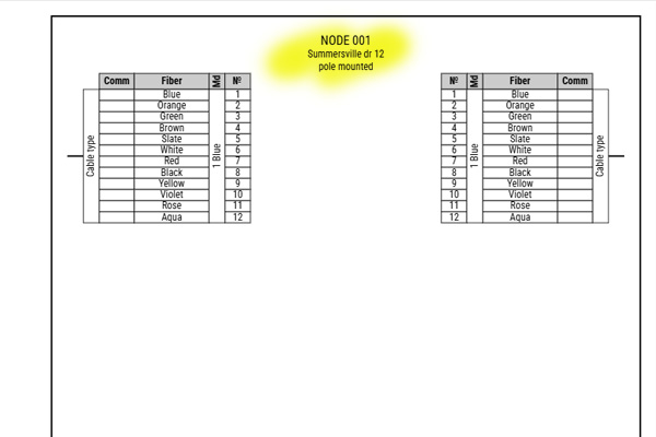
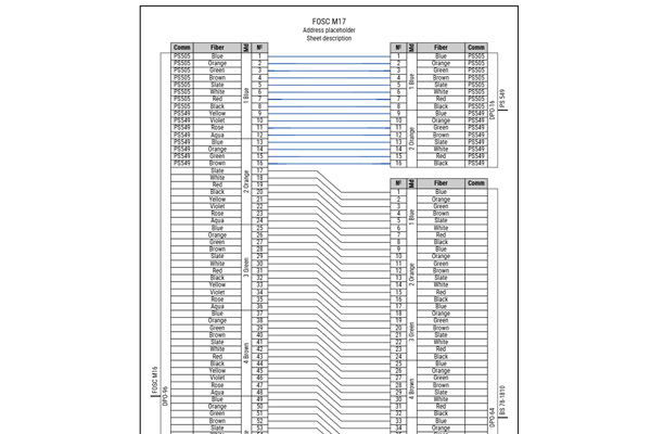
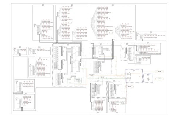
4. Diagram Structure (Sheet)
4.1. Each diagram should have a text title block on top of page, centrally aligned.
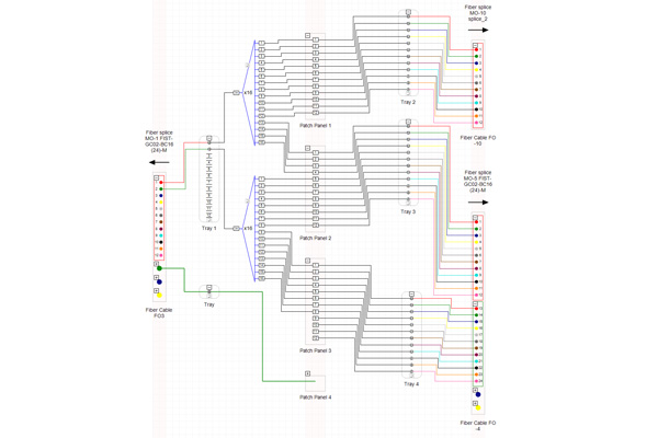
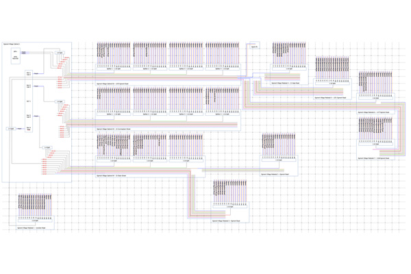
4.2. Optic cable faces and equipment should be represented vertically, positioned on both sides of the sheet, on the left and on the right, in two columns, forming a space for splices between them.
4.3. Optic cable faces and equipment should not be represented horizontally and should not be positioned on top or bottom of the diagram. Such positioning causes 90 degree splice bends, and multiple splice intersection form a rectangular grid, making splices visually untraceable and the diagram unreadable.
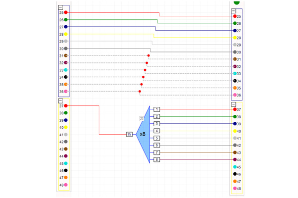
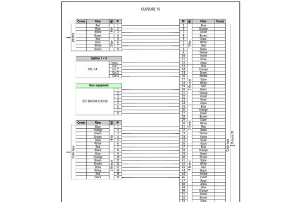
4.4. Nothing except splices should be placed in between cable faces or equipment in splicing area. Splitters, as well as any other equipment, should be placed in columns as per 4.2. Placing something in between columns causes clutter in the overall diagram readability.
✔️ Only splices in between
❌ Splitter between cables
4.5. Splices should have no more than 2 bends. Bend angles should be within 0-90 degree range. Splices should have at least 2 horizontal parts where they connect with cable face or equipment.
✔️ Correct splice geometry
❌ Incorrect splice geometry
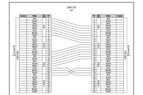
4.6. Cable face (or equipment) title block height, fiber heights, gaps between cables (or equipment) should be of the same size to maintain overall diagram cleanliness and to avoid excessive splice bends.
✔️ Well maintained layout
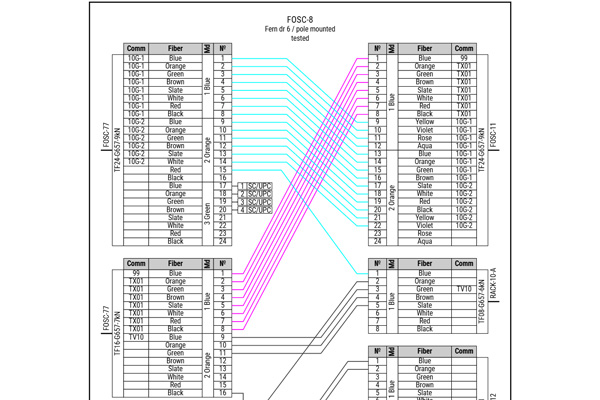
4.7. All the data in cable faces should be held bw (black and white). Coloring the text denoting the colors of individual fibers inside a cable is prohibited.
It is allowed to colorize splices between cables (or equipment), though it is prohibited to colorize splices in accordance with the cable’s color code.
✔️ Allowable splice coloring
❌ Forbidden splice coloring
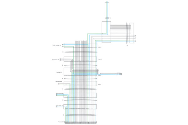
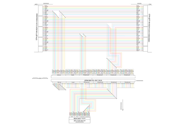
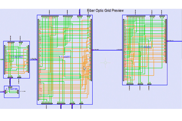
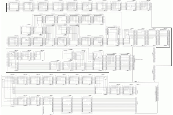
5. Diagram Structure (Bedsheet)
5.1. All sheets should be considered portrait orientated A4 size (or US letter size) sheets unless cables (or equipment) do not fit in them.
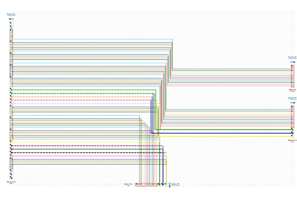
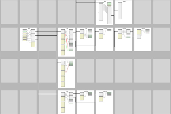
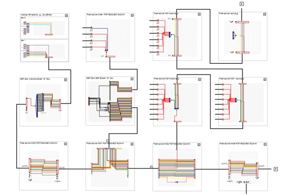
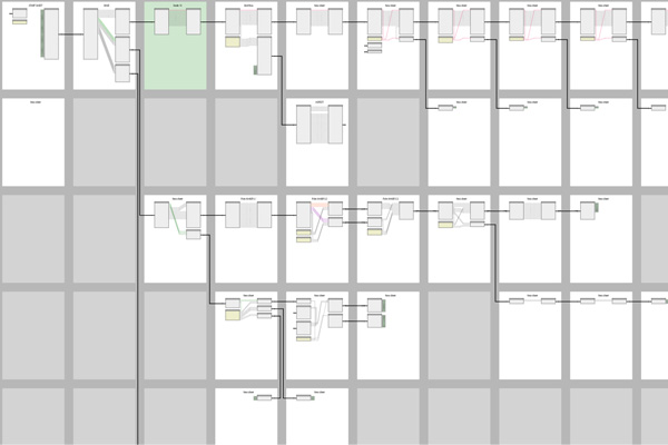
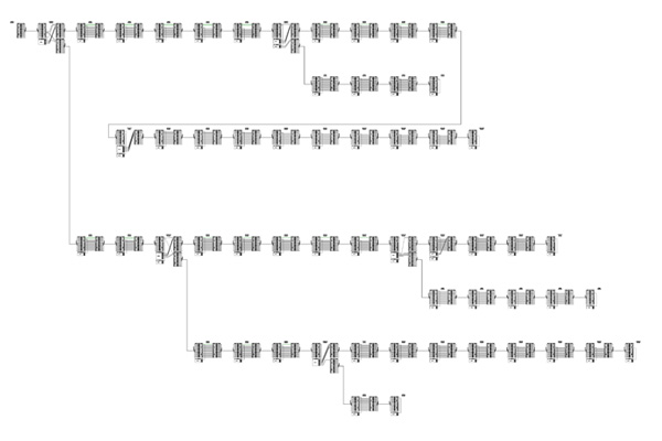
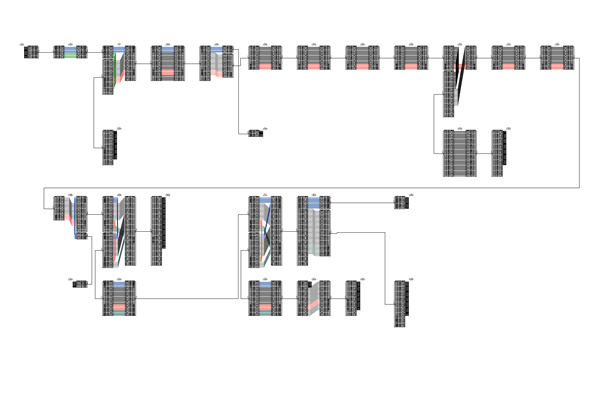
5.2. Sheets on a bedsheet should be positioned in a grid style.
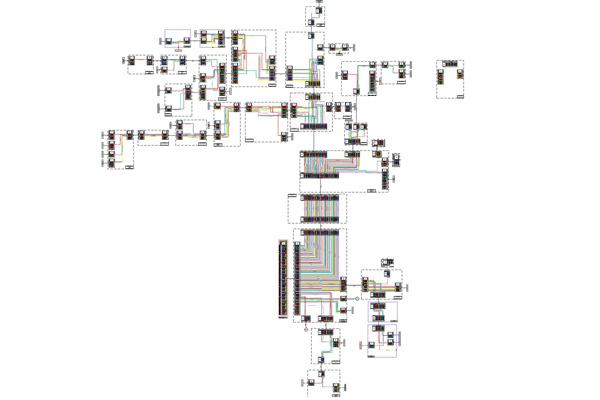
5.3. Sheets should be positioned in a way that they could be ”read” in rows from left to right. The whole diagram should be arranged in a way that rows could be read from top to bottom. Hence a central unit of a network should be placed in the top left corner, not in the center.
✔️ Proper sheet alignment
❌ Unreadable sheet alignment
5.4. Give your bedsheet “space to breath”.
6. Data Integrity and Validation
These rules serve these main purposes:
1. Unambiguity. Splice diagrams should be arranged in a way avoiding any possible misinterpretation of nodes, cables, equipment, fibers, their colors and paths, etc.
2. Clarity. A sneak peek at sheets and bedsheet should give an instant understanding of the network size and architecture. Fibers should be visually traceable. Everything should be clear.
3. Equality. Splice diagrams should be equally comfortable to use by designers and engineers in the office and by linemen and splicers in the field. Diagrams should be legible in both printed and digital formats.
Author
Vasiliy Grodetskiy
splice.me engineer
With over 20 years of experience in fiber network engineering, Vasiliy has been directly involved in the evolution and deployment of fiber infrastructure worldwide. Throughout his career, he has collaborated with literally hundreds of ISPs, network operators, and contractors across five continents, gaining a truly global perspective on network design and implementation.
Vasiliy brings deep expertise in industry standards, regulatory environments, and the practical trade-offs between different approaches to fiber network roll-out.