MS Visio has long been the default choice for drafting fiber network diagrams, and with the right stencil libraries it can be used to draw everything from backbone routes to detailed patch panel layouts. When fiber techs look for visio fiber stencils, they are usually solving a very practical problem – how to clearly document a fiber optic network using familiar tools. Hence searches for terms like fiber optic visio stencils, fiber patch panel visio stencil, or fiber ODF visio stencil are very common. However, as fiber networks grow in size and complexity, some engineers discover that Visio is better at initial drafting fiber than managing it.
Popularity of Visio fiber stencils
The popularity of visio fiber network stencils comes from flexibility and diversity. With the right stencil packs, engineers can quickly jump-start a big drawing from literally a blank page, and visually represent fiber optic cables, patch panels, splice trays, ODFs, network equipment, etc.
A typical workflow starts with drafting the structure of the network in coarse, adding previously saved stencils, downloading new stencils for new types of equipment, and connecting everything together into a cohesive network diagram. For low-level design, or early-stage, or even high level designs or documentation snapshots, this approach works well. With this approach a network tech can draft a comprehensive network diagram in minutes.
The majority of network equipment manufacturers usually supply visio stencils on their websites, you just have to search for them thoroughly.
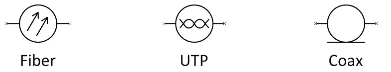
These shapes have connection points, so you can snap visio connectors to them.
Visio network diagram examples vs real networks
Most Visio network diagram examples found online represent a moment in time. They are often created for planning, presentations, or handover documentation. In real networks, however, fiber routes change, splices are reworked, capacity is adjusted. No fiber network stays the same and untouched for more than a week I’d say.
Every change requires someone to manually update a visio file. Over time, it becomes harder to trust that the diagram actually reflects the current state of the network. This is where many engineers begin to feel friction between what Visio shows and what exists in the field.
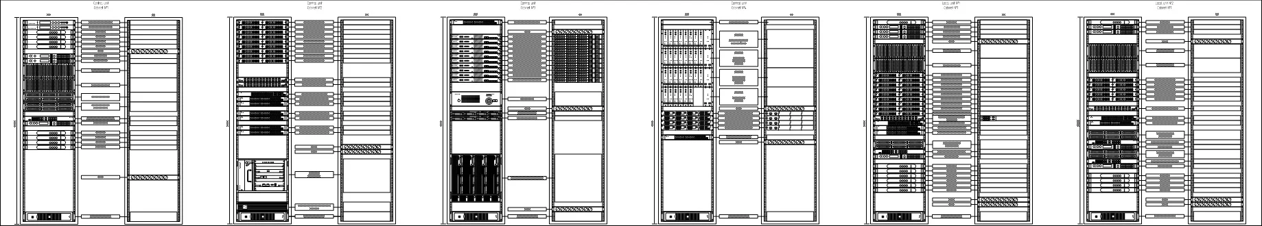
Visio works best when fiber documentation is simple and changes are infrequent. Say, drafting the front side of a 42U cabinet filled with network equipment – that’s what Visio is perfect for. Once a router will be replaced, or a server upgraded, an UPS added, such a drawing can stay barely touched literally for decades.
When Visio starts to break down for fiber networks
But when dealing with all sorts of fiber connections, problems start to appear. Multiple versions of the same diagram circulate, updates lag behind reality, and engineers spend more time maintaining drawings than working on the network itself.
Specialized tools like Splice.me are designed for exactly this problem. Instead of using Visio in general, or Visio fiber stencils to draw splice points, connections and splices themselves, Splice.me focuses on the ability to add data and adjust data in couple clicks. Fiber cables, fibers, splices, and routes become structured data rather than shapes on a page.
Many people still use Visio for high-level fiber design, mapping, etc., but rely on a fiber-specific SaaS to save enourmous amount of time dealing with splice charts.
You mean - don’t use Visio fiber stencils?
No! It’s completely OK to use them. If you are in the early stages of a network project, downloading fiber optic visio stencils and working through visio fiber network design makes sense. Visio remains a familiar and accessible tool for visual design.
But if your goal is long-term accuracy in the fast changing environment like fiber splice charts, stencils will still be eating too much of your time. And Splice.me tool exists not to replace Visio entirely, but to handle the complexity and speed that Visio is not designed for.

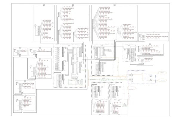
Splice.me app interface, which can replace a lot of Visio work