Areas of application
Single-span solutions are mainly used on long sections of submarine communication lines and on land sections passing through sparsely populated areas with harsh climatic conditions. In particular, they are used to connect islands, remote coastal cities, coastlines, and offshore oil platforms, as well as to create branches from submarine trunk lines. Another example: a large communications network based on single-span fiber optic lines connects a number of cities in the United Arab Emirates, separated by desert areas with very high daytime temperatures.
The record length of single-span line models obtained in the world’s leading research laboratories now exceeds 400 miles. However, to achieve such a long range, it is necessary to use remote optically pumped amplifiers (ROPA) and special optical fibers with low losses and a large core diameter. The practical use of such complex single-span communication line designs is economically justified only if other designs do not provide the required range and/or data transfer speed.
In practice, the required length of single-span communication lines (or the length of the longest sections of multi-span communication lines) can vary from 200 to 500 km. At the same time, it is often necessary to modernize the existing line by replacing the active equipment with more efficient equipment (with a channel speed of 100 Gbit/s) without modernizing the cable infrastructure.
Technological aspects
The transmission range in single-span communication lines is limited by the attenuation of the optical signal, which leads to a decrease in the optical signal-to-noise ratio (OSNR) below the minimum value required for the communication line to operate, which is commonly referred to as the «required OSNR» or OSNRR. This is a variable value that depends on various line characteristics (in particular, it increases with increasing signal power). The minimum OSNRR value is achieved in linear mode operation of a fiber-optic communication line with negligible nonlinear and linear signal distortions, when the receiver is connected to the transmitter by a very short fiber segment about one meter long. This OSNRR value is called the «required OSNR in a back-to-back scheme» and is denoted by OSNRR BtB. It is also called «critical OSNR» or OSNRT (from OSNR Tolerance). OSNRT is a constant for a given bit error rate (BER) that characterizes the quality of the transponder. Currently the world’s best OSNRT value is around 12.5 dB (for BER Range of 10..12).
Of greatest interest for single-span communication lines is counter-propagating Raman pumping (or Counter-Ramans pumping), since the pumping laser can be installed directly in the terminal node of the line on the receiver side. The same scheme can be applied on the transmitter side (co-propagating Raman pumping), although its effect may be less due to the noise introduced by the pump signal into the telecommunication signal.
The longest range is achieved using a remote-pumped optical amplifier, which is a section of erbium-doped fiber located about 100 km from the end of the line on the receiver side. The pump laser for the ROPA is located at the terminal node of the line, and the pump radiation is transmitted either through the telecommunications fiber or through an additional fiber to provide higher pump power. Before reaching the remote amplifier, the ROPA pump radiation in the telecommunications fiber also amplifies the signal due to the stimulated Raman scattering effect. Additionally, ROPA can also be used on the transmitter side.
Record-breaking single-span lines
Let’s consider options for organizing commercially effective long-distance single-span communication lines based on active DWDM equipment with a channel speed of 100 Gbit/s.
First successful record results in signal transmission at a speed of 100 Gbit/s over a distance of more than 500 km in a single-span line we achieved in 2010. In 2013, signal transmission in ten channels at a speed of 100 Gbit/s over a distance of 500 km was demonstrated. This was the world record by that moment. The experiment used 100G transponders (DP-QPSK modulation, coherent reception) and Corning SMF-28 ULL fiber with ultra-low attenuation and low polarization mode dispersion. The optical budget of the 10-channel line was 79 dB. The bit error rate (BER) in all ten 100G channels did not exceed the BER threshold throughout the entire experiment.
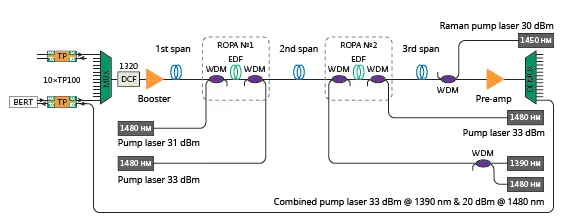
10 channels x 100G transmisson over 500km distance experiment
| Line | Span, km | Measured attenuation, dB | Linear attenuation, dB/km |
| First segment | 52.8 | 8.53 @ 1550 nm | 0.162 |
| Second segment | 303.3 | 47.30 @ 1550 nm | 0.156 |
| Third segment | 146.7 | 23.20 @ 1550 nm | 0.158 |
| ROPA delivery 1 | 50.5 | 8.03 @ 1550 nm | 0.159 |
| ROPA delivery 2 | 50.4 | 8.01 @ 1550 nm | 0.159 |
| ROPA delivery 3 | 147.6 | 28.00 @ 1480 nm | 0.190 |
| ROPA delivery 4 | 147.2 | 29.00 @ 1480 nm | 0.190 |
Segmant attenuation data
Typical single-span line configurations
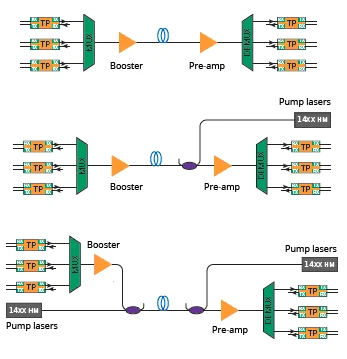
Various configurations can be used to organize long-distance single-span communication lines. In addition to erbium amplifiers at the line input (booster) and before the receiver (preamplifier), various additional signal amplification methods can also be used in long single-span lines, such as remote-pumped erbium amplifiers (ROPA) and distributed Raman amplification in telecommunications fiber.
Amplifiers can be pumped in both the forward direction (from the transmitter) and the reverse direction (from the receiver). Telecommunications fiber, in which the signal propagates, or additional fiber or fibers can be used to deliver the pump radiation. Thus, various schemes with different combinations of amplifiers can be implemented, each of which has its own characteristics.
Of greatest interest to telecom operators are schemes that allow a single-span line of maximum range to be organized using two fibers (one fiber in each direction). More expensive and complex solutions usually provide greater signal transmission range. At the same time, such solutions may significantly limit the number of DWDM channels. The selection and calculation of the optimal circuit must be performed by specialists, taking into account the specifics of each particular task.
Typical single-span lines without ROPA
In the simplest case, the fiber optic line is divided into two sections, between which a section of erbium-doped fiber is installed. This section of fiber is used as a remote-pumped erbium amplifier, which is injected into the fiber at a wavelength of 1480 nm in the opposite direction. In addition, thanks to pumping at a wavelength of 1480 nm, this scheme also provides additional signal amplification due to stimulated Raman scattering in the telecommunications fiber.
Finally, an even greater increase in range can be achieved by using additional Raman pumping In addition to pumping at a wavelength of 1480 nm in the opposite direction, pump radiation is also injected into the fiber in the same direction (at one or more wavelengths), which provides additional signal amplification due to Raman scattering in the telecommunications fiber.
To further increase the line length, the circuit needs to be further complicated: for example, using not one but two erbium amplifiers with remote pumping (B-ROPA and F-ROPA), additional Raman pumping in the opposite direction, etc. For example, to achieve a record signal transmission distance, scientists used a circuit variant with two ROPAs and counter-directional Raman pumping.
Single-span line based on standard fiber
In practice, the most interesting task is to create an extended single-span communication line based on existing fiber and without upgrading the existing cable infrastructure. In this case, the maximum range can be achieved using the scheme with co-propagating and counter-propagating Raman pumping.
The main difficulty in calculating such a line is to calculate the effect of co-propagating Raman amplification. The difficulty is due to the fact that the signal power, and therefore the weight of nonlinear effects, increases at the beginning of the line due to co-propagating pumping and reaches its maximum value at a distance of approximately 20 km from the beginning of the line. To correctly account for the influence of nonlinear effects in a DWDM system with M channels and K pumping sources, a numerical solution of a system of M + K differential equations is required.
Calculating the influence of counter-Raman amplification is much simpler, since the signal is in linear mode at the end section of the line. Counter-Raman amplification is usually taken into account as an additional amplifier with a noise factor of about -1,5.
Conclusion
We have verified that when constructing single-span lines, the use of standard fiber with an attenuation of 0.22 dB/km and Raman pumping allows for the transmission of 40 DWDM channels in one span over a distance of 250 km with a 3 dB margin. To achieve record transmission distances in a single span, it is necessary to use special fiber with ultra-low attenuation and erbium amplifiers with remote ROPA pumping. The possibility of transmitting 1 Tbit/s (10 channels of 100G) in a single-span line with a length of more than 500 km was experimentally proven. In practice, long-distance single-span line designs are developed individually for each specific situation.
Continue learning:
Learn about fiber optic cable quality assessment
Learn about fiber assemblies for trunk cables
Learn about reduced size fiber optic cables
Learn about the evolution of standard optical fibers
Take care of your splice sheets
1000+ ISPs are already saving weeks of work with Splice.me!