Reduced size fiber optic cables with round wire armor

The results of the development of small-sized optical cables with round steel wire armor are presented. Their design and manufacturing technology ensure high mechanical parameters -allowable working load under elongation, transverse strength, and good flexibility.

The design of fiber optical cables (FOC) with round wire armor is almost always associated with fairly large and massive products intended for underground installation (including in sewers, pipes, blocks, collectors, in soils of all categories, in water when crossing swamps, lakes, and rivers). These FOCs are also used for operation in extreme conditions and can usually contain one or two layers of steel wire strands.

In these designs, consumers are offered versions in which wire with a diameter of 0.2-0.8 mm is present in the form of winding or braiding. Its main function is to protect against rodents or the impact of installation tools. In all these cases, the armor protects the cable from tensile forces, as well as from shear forces, but is not sufficiently effective against crushing loads.

The crushing resistance of fiber optic cables can be increased by increasing the diameter of the steel wires and/or reducing the winding pitch. Both of these measures lead to an increase in the weight and overall dimensions of the cable. In addition, the speed of the round wire armoring process is low, which significantly reduces the overall production speed. The speed of braiding machines is also extremely low. Armoring of FOC requires the use of complex, expensive, and energy-intensive machines.

Based on the above considerations, the task was formulated to create an armored FOC that best meets the following requirements:
  • maximum possible mechanical strength with minimum (less than 0.5%) relative elongation;
  • minimum weight and dimensions;
  • high manufacturability;
  • minimum cost.

At the same time, the optical cable must satisfy such principles of unified fiber-optic communication network construction as miniaturization, universalization, multifunctionality, and manufacturability. As noted earlier, the contribution of wire armor to ensuring the strength of the FOC under tensile forces is quite significant and can be decisive. The central element may also play a role. Ultimately, their presence reduces the flexibility of the fiber cable design. And while this is not particularly critical for trunk cables, it can create certain difficulties for other areas of FOC application, such as field communications, chemical and mining industries, “on-board” cables, etc.

The problem of increasing flexibility can be solved by eliminating the central strength member, including multi-module FOC designs. In this case, the armored coating protects the optical cable from tensile loads and acts as an anti-shrinkage element, holding the polymer modules located inside the armored coating during their thermal shrinkage. This results in a reduction in weight and dimensions of the optical cable.

Some work has been done to increase the flexibility and transverse stability of the optical cable by winding wire with a minimum pitch onto the optical core of the optical cable. A special installation was developed for this purpose, but the resulting cable designs were not in demand.

Attempts were made to replace the steel wire armor in the cable with thin metal tubes, which significantly increased resistance to crushing loads and, to some extent, increased performance. Metal sheaths also acted as a protective barrier against moisture penetration in the radial direction. Work in this direction was carried out for quite a long time. Copper, aluminum, and steel were used to manufacture metal “tube modules.” In the 1990s samples of stainless steel tubes were manufactured.

FOC designs with metal “tube modules” returned after 20 years, but their function is more related to protecting optical fiber itself from moisture, aggressive environments, and increasing heat resistance (fire resistance). But they cannot provide the same level of flexibility. Cables with metal tubes have found application in a number of critical products, but they do not solve the task at hand. Today, it is clear that steel wires must be used to create flexible armored cables that are comparable in flexibility to unarmored versions. The task is to create an armor design that meets this requirement and increases the speed of armoring to the average speed of applying an outer hose. Having formulated the task, it is possible to find an acceptable solution, which consists in changing the technological scheme of cable manufacturing – replacing the sequential scheme with a parallel one.

In a sequential scheme, the armor is formed on the surface of the element that is being armored (cable twist, inner sheath, etc.). In this case, the armoring operation determines the speed of cable manufacturing.

The essence of the parallel scheme is to separate the most labor-intensive operation into a separate one, followed by the inclusion of the resulting semi-finished product into the general technological line. In this case, by creating a certain stock of semi-finished products, it is possible to regulate the speed of the general technological process of FOC manufacturing.

A scheme for creating armor as an independent action was proposed. The subsequent technological operation involves inserting a twist of cable elements and hydrophobic or other filling into the formed armor. As a result, a high-speed scheme for manufacturing FOC was implemented with the formation of armor wrapping resistant to crushing (transverse) loads. Due to this blog post space limitations, this article does not provide mathematical calculations based on Kirchhoff’s equation.

Note that in the calculations, the radial load is perpendicular to the axis of the armor coil spiral, and using a system of linear equations, it is possible to determine the critical values of the load on the spiral turn at which it loses its stability. This critical load depends on the angle of the spiral winding, as well as the shape and dimensions of the turns and the characteristics of the material. As a result of the calculations, the optimal spiral winding angle was determined, which for round wire is 57 degrees.

Based on the results of the research, three basic FOC designs were developed, which largely meet the four requirements and five principles formulated above.
steel wire armored fiber optic cable 01

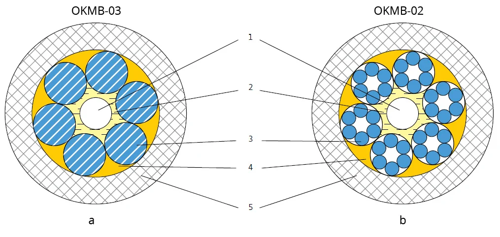
Pic. 1 OKMB-03 and OKMB-02 cable designs
1 – quartz fiber optic cables in a varnish coating (SM or MM)
2 – hydrophobic filler
3 – armor coating made of galvanized steel wires or wire strands
4 – outer hydrophobic filler
5 – hose

In the OKMB-03 design (pic. 1a), the optical fibers are located freely directly inside an armored tube made of steel rope wires.

In the second design, OKMB-02 (pic. 1b), the optical fibers are freely located directly inside an armored tube made of steel wire strands.

During the manufacturing process, a ready-made seven-wire or seven-strand rope with a diameter of 2.4 mm is used. This initial rope, up to 8 km long, is installed as a feeder on the production line, then six wires of the outer layer of this rope are twisted and the armor is formed directly over the four optical fibers (the fibers are inside the rope). The result is a flexible steel «tube – metal module» with a hole, inside which the fibers are located, and the free space is filled with a hydrophobic compound.

The described technological process is carried out in one stage at an average speed of 5 to 25 meters per minte, depending on the diameter of the module (or cable).

The hose material is UV-resistant polyethylene or a polymer that does not support combustion and does not emit halogen-containing toxic substances. FOCs do not contain tubular polymer optical modules, which increases their fire resistance.

The second of the designs mentioned, OKMB-2, is more flexible.

The absence of a polymer module and the durable armor of the FO cable allow for minimizing the dimensions and weight of the FO cable, while ensuring high mechanical parameters – allowable working load under elongation, transverse strength, and good flexibility.

The main characteristics of these cables are:
  • diameter of the armor coating – from 1.0 to 4.0 mm;
  • number of fibers – up to 16;
  • maximum allowable tensile load – up to 9 kN;
  • allowable transverse pressure – 5 kN/10 cm;
  • operating temperature range – -60..+70 °C;
  • outer diameter – up to 7.0 mm.
The usual thickness of the polymer sheath is up to 0.8 mm.

Such cables are usually very difficult to damage during installation and operation, and therefore they can be used in various conditions – in communication ducts, for laying in the ground, in asphalt, for overhead install, laying inside buildings and premises, etc. Thus, these FO cables are universal in application. The main design parameters of OKMB cables are given in Table 1.
Cable type Fiber count Breaking strength, kN Cable weight, kg Armor diameter, mm Cable diameter, mm
OKMB-03 1 0.6 – 1.0 8.5 – 15 1.2 – 1.6 1.8 – 2.6
OKMB-03 2 2.0 25 2.0 3.2
OKMB-03 4 2.5 32 2.4 3.6
OKMB-03 8 3.5 – 4.5 40 – 45 2.8 – 3.1 4.2 – 4.7
OKMB-03 12 5.0 – 6.0 60 – 72 3.3 – 3.7 4.9 – 5.1
OKMB-03 16 6.0 – 7.0 72 – 85 3.7 – 4.0 4.7 – 5.5
OKMB-01 1 0.5 15 1.5 2.6
OKMB-02 2 1.0 20 2.0 3.2
OKMB-02 4 2.0 28 2.4 3.6
OKMB-02 8 2.5 35 2.9 4.1
OKMB-02 12 3.0 50 3.3 4.7
OKMB-02 16 4.0 60 3.7 5.5

In the third basic design of optical cable – OKPB (pic. 2) – the optical fibers are located inside a polymer tube. The armor consisting of 12 or 18 steel wires is twisted over the tube. The difference in design is that the armor layer is not made by twisting, but using the technology discussed earlier. As in OKMB cables, the armour braid is not made from individual wires, but is twisted directly from ready-made metal ropes, and has either 12 or 18 wire braids made from preformed steel wires with a diameter of 0.6 to 1.0 mm. The diameter of the cable is from 3.0 to 5.0 mm with an allowable tensile load of up to 10 kN.

steel wire armored fiber optic cable 02

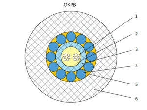
Pic. 2 Cables with a central polymer module
1 – quartz fiber optic cables in a varnish coating (SM or MM)
2 – intra-module hydrophobic filler
3 – polybutylene terephthalate (PBT) module
4 – armor coating made of galvanized steel wires
5 – outer hydrophobic filler
6 – hose

To increase the allowable tensile load, cables with an additional armored layer can be manufactured at the customer’s request. OKPB and OKP2B cables differ from similar FOC designs in their high mechanical characteristics in terms of tensile and transverse forces, flexibility, resistance to twisting and bending, high quality, and relatively small weight and size.

The main characteristics of these cables are:
  • diameter of the first armor coating – from 3.0 to 5.2 mm;
  • fibers used – MM and SM with lacquer coating according to G.652, G.657 specs;
  • number of optical fibers – from 1 to 32;
  • allowable tensile load:
  • from 2.5 to 10 kN – for single-layer armor;
  • from 12 to 20.0 kN – for double-layer armor;
  • allowable transverse crushing force – from 3 to 10 kN/10 cm for single-layer armor;
  • operating temperature range – -60..+70 °C;
  • outer diameter – from 3.0 to 9.0 mm (for FOC with single-layer armor).
Cable type Fiber count Breaking strength, kN Cable weight, kg/km Module diameter, mm Armor diameter, mm Cable diameter, mm
OKPB / 2.5 kN 6 2.5 40 1.8 3.0 4.2
OKPB / 3.0 kN 8 3.0 45 2.0 3.3 4.5
OKPB / 3.5 kN 8 3.5 52 2.1 3.6 5.6
OKPB / 5.0 kN 12 5.0 75 2.4 4.0 6.6
OKPB / 7.0 kN 16 7.0 92 2.75 4.6 7.0
OKPB / 8.0 kN 24 8.0 115 3.0 5.0 8.0
OKPB / 10.0 kN 32 10.0 140 3.4 5.2 9.0

Conclusion
OKPB cables with single-layer armor can be used in urban communication networks. OKP2B cables with double-layer armor can be used for critical installations, including harsh soil conditions. The developed designs create a basis for a significant reduction in the range of cable products and allow for comprehensive and cost-effective solutions to the tasks at hand.

Take care of your splice sheets

1000+ ISPs are already saving weeks of work with Splice.me!

Share

Read more