The length of individual optical fibers in trunk cables can be adjusted in various ways to ensure that the specified optical skew parameter is achieved.
The response time of a data center (DC) to an incoming user request, which is one of the main criteria for the quality of its operation, requires the use of communication channels with a speed of 40+ Gbit/s. Given the capabilities of modern microelectronics, such value can only be achieved in mass-produced equipment on the basis of parallel transmission. Two types of such transmission, based on spatial and spectral multiplexing, have been widely adopted in engineering practice.
Given the short lengths of the paths within the data center, a spatial multiplexing scheme with a speed of about 400 Gbit/s is more economically attractive, although even at a speed of 100 Gbit/s it is often combined with spectral multiplexing (WDM).
Satisfactory economic parameters for spatial multiplexing equipment can only be achieved if the «optical delay skew» parameter (79 ns/100 m) is complied with. The simplest way to solve this problem is to forcibly align the physical lengths of individual optical fibers (OF) by forming assemblies. This can be done in various ways.
Ribbon optical fibers
Minimal optical skew is relatively easy to achieve in classic ribbon optical fibers. Using this type of fiber assembly as the basis for the core design of trunk cables is also advisable because it does not require new developments: the components are simply borrowed from general-purpose cables.
When forming a ribbon light guide, individual fibers are laid parallel to each other at a certain pitch, after which they are fastened in one way or another. The secondary protective coating takes on the function of mechanically fixing individual optical fibers in the ribbon structure. The secondary protective coating of ribbon structures can be implemented in different ways.
The first method introduced into widespread engineering practice was developed by AT&T Bell Labs. It is based on sticking individual optical fibers onto a polyester resin (acrylate) film. To achieve higher mechanical stability, double-sided adhesive tape was used, i.e., the fibers were located between two tapes (pic. 1a).
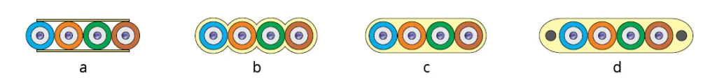
Pic. 1.
a – based on gluing onto film
b – with filling of the interfiber space with polyester resin
c – enclosed in a shared sheath
d – with reinforcing elements to increase tensile strength
The main disadvantage of this method was the low mechanical strength of such a structure, primarily its weak resistance to lateral shear forces. This disadvantage was eliminated by switching to a scheme of filling the gap between individual light guides with acrylate (pic. 1b).
Another option for the ribbon design was to place a group of parallel fibers in a common sheath with a smooth surface (pic. 1c). This design enhances protection against external mechanical influences and hardly increases the external dimensions of the product.
The number of fibers in a single ribbon depends on the purpose of the fiber optical cable (FOC), the selected communication scheme, and can be 2, 4, 6, 8, and 12. In trunk cables for external deployment, 24-fiber ribbons are often used. For intra-facility trunk FOC systems of parallel transmission, ribbons with 8, 12, and 16 fibers are used. If it is necessary to increase the number of optical fibers, several identical tapes are inserted into the core of the trunk cable.
The ribbon’s resistance to tensile forces is increased by increasing its width and adding two strength elements located at its edges (pic. 1d).
The main advantage of forming a core based on ribbon optical fibers is the possibility of achieving a very high overall density of the structure. This is most evident in optical cables with a large number of fibers. If we compare products with similar characteristics, the ribbon design exceeds the traditional multi-module design in terms of construction density by approximately 3.5 times, while being at least equal in other characteristics (table 1).
| Parameter | Modular | Ribbon |
| Fiber count | 62 | 432 |
| Outer diameter, mm | 21.3 | 14.2 |
| Density, mm2/fiber | 1.26 | 0.37 |
| Cable weight, kg/km | 370 | 328 |
| Tensile strength, N | 2700 | 2700 |
- the cross-section differs from a round shape (with a small number of fibers);
- the complexity of splicing and field installation of MPO/MTP connectors.
Quasi-modular design
- using the same type of optical fibers;
- the regular arrangement of the fibers;
- the tight coverage of the optical fibers by the outer shell.

Pic. 2. 4-fiber round structure “j-FiberUnit”
SpiderWeb technology
This technology was developed by Fujikura to improve the weight and size characteristics of multi-fiber optical cables. The SpiderWeb optical fiber ribbon includes 12 fibers in the primary protective coating. Adjacent fibers are mechanically bonded to each other over a short section of the cladding. To increase the resulting density of the structure, the ribbon is rolled into a tube according to the 3-4-3-2 scheme (pic. 3) and placed inside a protective sheath with a relatively small diameter.

Pic. 3. Some features of SpiderWeb ribbon
a – structure of a 12-fiber ribbon in a coiled state
b – fragment of the ribbonin a straightened and stretched state
When stretched, the ribbon becomes a mesh. If necessary, the fibers can be easily separated from each other by a simple pulling motion, which breaks the fixing bridge. The ribbon structure used by the manufacturer, combined with the absence of a secondary protective coating, not only gives the product very low rigidity, but also allows it to bend with a fairly small radius.
The absence of a secondary protective coating significantly improves the weight and size characteristics of the cable. For example, a 1728 ct outdoor fiber cable with a tensile strength of 2700 N, which is typical for such products, has a diameter of only 21.8 mm (a 40% advantage over similar products) with a linear weight of 340 kg/km (a 3.0 times advantage over multi-tube ribbon designs). The large width of the ribbon allows for effective color coding of the primary protective coating.
From the point of view of parallel transmission, the mechanical connection of individual optical fibers to each other is of great importance. This makes it much easier to achieve the minimum optical skew value. Therefore, SpiderWeb ribbons can be used to organize 500-meter single-mode connection lines permitted by the standards.
SpiderWeb technology offers the greatest advantages when manufacturing outside plant FOCs with a large number of fibers. In addition, the ribbon structure is fully compatible with the ribbon splicing machines.
For DC connections and similar facilities with low fiber density and no splicing work, the product does not offer any particular advantages. The exception is the round cross-section shape. Multimode trunk cables with an outer diameter of 3 mm based on SpiderWeb ribbon and reinforced with kevlar braiding in 12- and 24-fiber versions are offered by the AFL company.
Securing fiber ribbons taps
In parallel transmission technology, various cords and linear cables with an «Т to M» configuration are popular, in which at least one of the parameters (N or M) differs from one.
Cable products for parallel transmission are mainly based on ribbon optical fibers. Due to the high density of individual fibers adjacent to each other and the integral nature of the ribbon, separating individual groups of optical fibers from it, which is required for making taps, becomes a difficult task. Several approaches have been proposed to solve this problem, which significantly simplify the implementation of this procedure.
The first option is based on placing separate mechanically unconnected ribbons inside a shared sheath. In fact, a ribbon microcable is implemented in the form of a so-called split ribbon cable (pic. 4a).
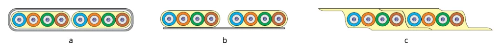
Pic. 4. Ribbon fiber optic cable design options for easier branching
a – in a common sheath
b – with gaps between individual groups
c – with a shaped outer surface of the ribbon
Separate fiber groups can be easily separated from each other if they are initially part of a shared ribbon but are spaced apart (for example, as shown in pic. 4b). Direct use of such a ribbon is impractical due to its big dimensions and increased “brittleness” in the transverse direction. To eliminate these disadvantages, it is possible to switch to a ribbon with two side wing-taps and corresponding recesses on the outer surface. The wings and recesses can be formed by increasing the thickness of the bonding sheath, as shown in pic. 4c. The resulting structure is used to fasten individual groups of optical fibers to each other, increasing its transverse stiffness. At the same time, this design of the ribbon fiber makes it easy to separate groups of optical fibers if necessary.
Conclusions
1. Mass produced fiber assemblies for trunk cables provide a 7–10-fold margin in terms of skew, which can be used to increase the communication range.
2. The development of specialized optical fibers for parallel transmission trunk cables is moving in the direction of creating structures that allow for the most efficient round cross-section for operation.
3. The task of separating individual fibers from a group, which is necessary for creating taps, can now be considered fully solved.
Continue learning:
Learn about fiber optic cable quality assessment
Learn about reduced size fiber optic cables
Learn about the evolution of standard optical fibers
Learn about long-distance single-span fiber optic lines
Take care of your splice sheets
1000+ ISPs are already saving weeks of work with Splice.me!